Modbus RTU Explained: Registers, Addresses, Frames, CRC

The short answer
Modbus RTU is a master/slave protocol, usually over RS-485, in which one master polls up to 247 slave addresses with short binary frames: slave address, function code, data and a 2-byte CRC. Each slave exposes four data tables: coils, discrete inputs, input registers and holding registers. The manual address 40001 means holding register at offset 0 on the wire, which is why a value read "one register off" is the most common Modbus mistake.
Watch the lesson
The video above is How does Modbus Communication Protocol Work? by RealPars, embedded with thanks. EDWartens is not affiliated with the creator. It is about 12 minutes long and is used in the free Industrial Communication course.
The lesson works through what Modbus is, the master and slave model, how devices are addressed, the data the protocol carries, and how a message is built and checked. It is a gentle introduction; the written part below goes further into the details you need on site: the addressing off-by-one, the frame byte by byte, 32-bit values and exception codes.
How a Modbus RTU network works
- Physical layer: RS-485, two wires plus a common, multi-drop. One segment supports 32 standard unit loads without a repeater; Modbus addresses run from 1 to 247, with 0 reserved for broadcast writes.
- Who talks: only the master starts a conversation. A slave answers only when addressed. Slaves never talk to each other.
- Serial settings: every device on the bus must match baud rate (9600 and 19200 are common), data bits (8), parity and stop bits. The Modbus specification's default is even parity; no parity with 2 stop bits is the standard alternative, though many devices ship set to no parity and 1 stop bit.
- Timing: a frame ends when the line goes silent for at least 3.5 character times. At 9600 baud with 11-bit characters that is about 4 ms; above 19200 baud the specification fixes it at 1.75 ms.
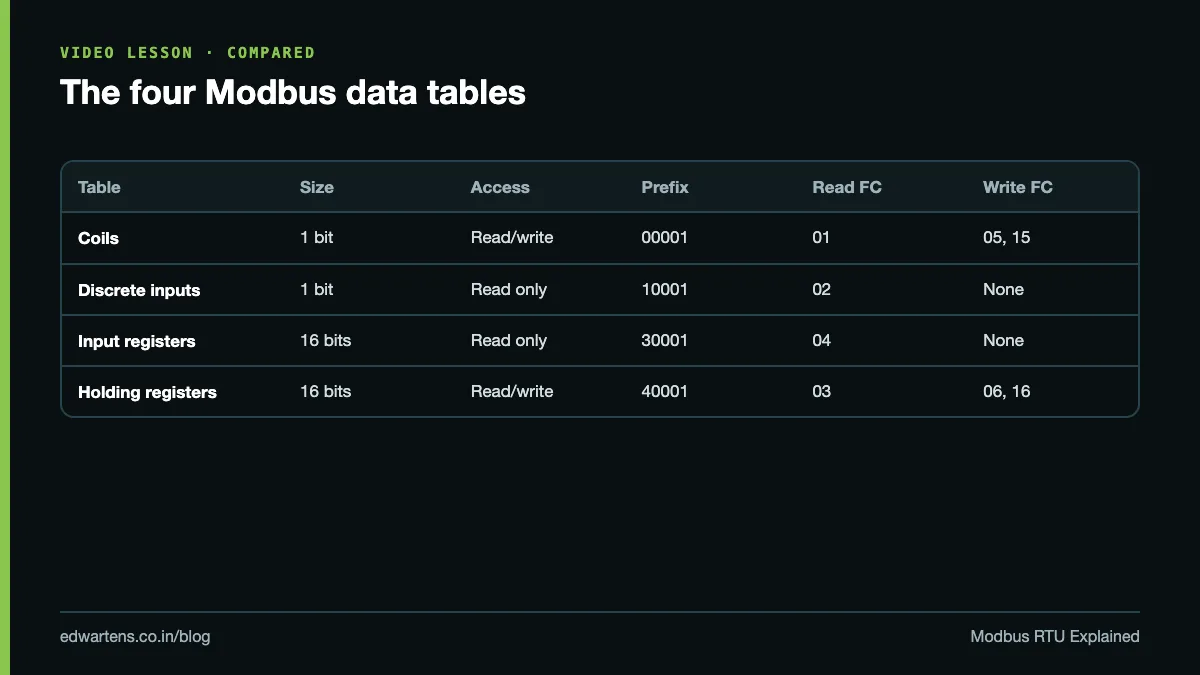
The four data tables
| Table | Size | Access | Manual prefix | Read FC | Write FC |
|---|---|---|---|---|---|
| Coils | 1 bit | Read/write | 0xxxx (00001) | 01 | 05 single, 15 multiple |
| Discrete inputs | 1 bit | Read only | 1xxxx (10001) | 02 | None |
| Input registers | 16 bits | Read only | 3xxxx (30001) | 04 | None |
| Holding registers | 16 bits | Read/write | 4xxxx (40001) | 03 | 06 single, 16 multiple |
Typical use: coils for run/stop commands, discrete inputs for status bits, input registers for measurements, holding registers for setpoints and configuration. Many devices, especially drives and energy meters, put everything in holding registers and read it all with function code 03.
Addressing: 40001 versus offset 0
This is where most new engineers lose an afternoon. There are two numbering systems:
- Manual (data model) numbering, one-based with a table prefix: 00001, 10001, 30001, 40001. Device manuals often use it. Six-digit forms such as 400001 exist for maps with more than 9,999 registers.
- Protocol (wire) addressing, zero-based, with no prefix: the function code already says which table, and the address field carries an offset from 0 to 65535.
So holding register 40001 travels as function 03 with address 0. Holding register 40101 travels as address 100 (hex 0064). Input register 30005 travels as function 04 with address 4.
| Manual says | Function code | Address on the wire |
|---|---|---|
| 00001 (coil 1) | 01 or 05 | 0 |
| 10010 (discrete input 10) | 02 | 9 |
| 30001 (input register 1) | 04 | 0 |
| 40001 (holding register 1) | 03 or 06 | 0 |
| 40101 (holding register 101) | 03 or 06 | 100 |
The trap: some manuals list wire offsets, some list one-based numbers, and some list one-based numbers without the 4 in front. Software varies too. Some master configurations ask for 40101, some for 100, some for 101. If the value you read is plausible but belongs to the neighbouring parameter, you are one off. Shift by one and try again, then write down which convention that device and that master use.
The RTU frame, byte by byte
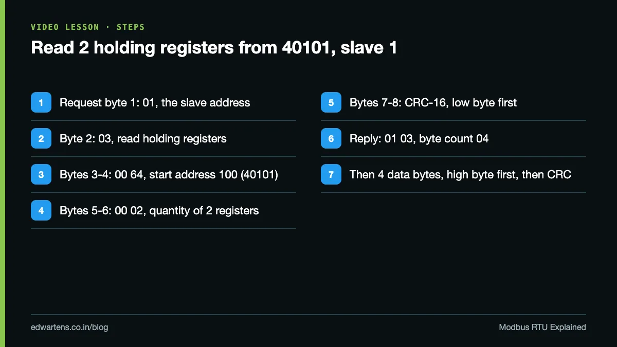
Read two holding registers starting at 40101 from slave 1. The request is eight bytes:
| Byte | Value (hex) | Meaning |
|---|---|---|
| 1 | 01 | Slave address |
| 2 | 03 | Function: read holding registers |
| 3 to 4 | 00 64 | Starting address 100 (that is 40101) |
| 5 to 6 | 00 02 | Quantity: 2 registers |
| 7 to 8 | CRC low, CRC high | CRC-16 over bytes 1 to 6 |
The response is: 01, 03, a byte count of 04, then four data bytes (two registers, each sent high byte first), then the CRC. One function 03 request can read up to 125 registers.
The CRC is a 16-bit cyclic redundancy check calculated over every byte before it, sent low byte first. The receiver recalculates it; if it does not match, the slave discards the frame and says nothing. That silence is why a noise or wiring problem shows up in the master as a timeout, not as an error message.
Modbus TCP in one paragraph
Modbus TCP carries the same function codes and data tables over Ethernet on TCP port 502. The slave address and CRC are replaced by a 7-byte MBAP header: transaction ID, protocol ID, length and unit ID. Ethernet handles error checking, so there is no CRC. Gateways translate between the two, and the unit ID tells the gateway which RS-485 slave to forward to. For where Modbus TCP sits against PROFINET, read PROFINET vs PROFIBUS vs Modbus TCP.
32-bit values over two registers
A register holds 16 bits. Energy counters, floats and anything bigger need two registers. The bytes inside each register are always high byte first, but the order of the two registers is not standardised. Suppose a meter's manual lists active energy as a 32-bit float at 40101 and 40102:
- Read 2 registers starting at wire address 100.
- Combine them high word first and decode as a float.
- If the result is a huge or tiny nonsense number, swap the two words and decode again.
- If it is still wrong, check the offset (try 99 and 101) and the data type (float, signed or unsigned integer, scaled integer).
Most PLC and SCADA drivers, Ignition and Node-RED included, have a word-swap option for exactly this reason.
Exception codes
If the slave received a valid frame but cannot do what was asked, it replies with the function code plus 0x80 (so 03 becomes 83) and an exception code:
| Code | Name | Usual cause |
|---|---|---|
| 01 | Illegal function | Device does not support that function code |
| 02 | Illegal data address | Register does not exist: often the off-by-one |
| 03 | Illegal data value | Value or quantity out of range |
| 04 | Slave device failure | Internal error in the device |
No reply at all is different: wrong slave address, wrong serial settings, wiring, termination or CRC errors. For that side of the problem, follow our Modbus RTU troubleshooting guide, which covers termination, biasing and CRC errors.
Common mistakes
- One register off. The classic. Check the manual's numbering convention against the master's.
- Reading input registers with function 03. The data is in 3xxxx, so it needs function 04. You get exception 02 or the wrong data.
- Mismatched parity. One device at 8-N-1 on an 8-E-1 bus never answers.
- Two slaves with the same address. Both answer, the replies collide, and the CRC fails.
- Word order guessed, not tested. Prove 32-bit values against the device's own display before you trust them.
- Polling too fast. Leave time for slow devices to respond; a timeout shorter than the device's reply time looks like a dead slave.
Practice task
Write a Modbus map for a VFD with four items: a run command, a frequency setpoint in 0.01 Hz, a status word, and a 32-bit energy counter. For each, give the table, the manual address, the wire address, the function codes to read and write, the data type and the access (read or read/write). Done means every wire address is the manual number minus the table base, and the energy counter takes two registers with its word order noted.
Learn it free
The free Industrial Communication course covers serial, Modbus RTU and TCP in depth, with written notes and a practice task. To read Modbus data into a dashboard, the free Node-RED for Industrial IoT and Ignition SCADA courses both use it, and our walkthrough on how to read a PLC with Node-RED and build a dashboard is a good next project.
Frequently asked questions
Q: What does 40001 mean in Modbus?
A: It is holding register number 1 in the one-based manual convention. On the wire it is function code 03 or 06 with address 0.
Q: What is the difference between holding registers and input registers?
A: Holding registers (4xxxx) are read/write and use function codes 03, 06 and 16. Input registers (3xxxx) are read only and use function code 04.
Q: How many devices can be on one Modbus RTU network?
A: Modbus allows slave addresses 1 to 247, but a standard RS-485 segment supports 32 unit loads, so more devices need repeaters or low-load transceivers.
Q: Why does my Modbus value look right but belong to the wrong parameter?
A: You are almost certainly one register off because of the one-based versus zero-based addressing. Shift the address by one and compare with the device's display.
Q: Does Modbus TCP use a CRC?
A: No. Modbus TCP replaces the slave address and CRC with a 7-byte MBAP header and relies on Ethernet and TCP for error checking.
Learn this, free
The courses that teach this
Every lesson, the written notes and the practice are free with an account. Only the certificate is optional and paid.