PLC counters explained: CTU, CTD and CTUD with examples

The short answer
A CTU (count up) adds 1 to its accumulated or current value on every false-to-true transition of its input and sets its done output when the count reaches the preset. A CTD (count down) subtracts 1 per transition; a CTUD does both, with separate up and down inputs. A reset input clears the count to zero, and on IEC counters a load input copies the preset into the count. Because an ordinary counter sees its input only once per scan, it cannot count pulses that are shorter than one scan; faster signals need a high-speed counter.
The words every counter uses
| Term | Siemens (IEC) | Allen-Bradley | Mitsubishi FX | Meaning |
|---|---|---|---|---|
| Preset | PV | .PRE | K value or D register | The target count |
| Current count | CV | .ACC | Current value of Cn | How many have been counted |
| Done | Q (QU, QD) | .DN | Contact Cn | Target reached |
| Reset | R | RES instruction | RST Cn | Count back to zero |
| Load | LD | Move into .ACC | Move into Cn | Count set to the preset or a value |
Counters count transitions, not levels: holding the input on for an hour adds exactly one, whereas an ADD instruction runs on every scan the rung is true.
How each counter behaves
CTU: count up
Each rising edge on CU adds 1 to CV. Q (or .DN) turns on when CV is greater than or equal to PV and stays on while the count stays there. On Siemens IEC counters CV stops at the top of its data type; on Allen-Bradley the count carries on past the preset and keeps .DN on. R clears CV to zero and Q off.
CTD: count down
Each rising edge on CD subtracts 1. On the IEC CTD, LD copies PV into CV, and Q turns on when CV is less than or equal to zero. So the usual pattern is: load 12, count down as items leave, and Q says "none left".
Allen-Bradley is different and catches people out: CTD has no load input, and its .DN bit is still set when .ACC is greater than or equal to .PRE, the same test as CTU. To count down from 12, move 12 into .ACC and compare .ACC with LEQ 0 rather than relying on .DN.
CTUD: up and down
The IEC CTUD has CU, CD, R, LD and PV inputs and two outputs: QU (CV greater than or equal to PV) and QD (CV less than or equal to zero). R has priority over LD. If an up edge and a down edge arrive in the same scan, CV is unchanged, which is the correct answer for one part in and one part out.
Syntax by brand
Siemens TIA Portal: IEC counters
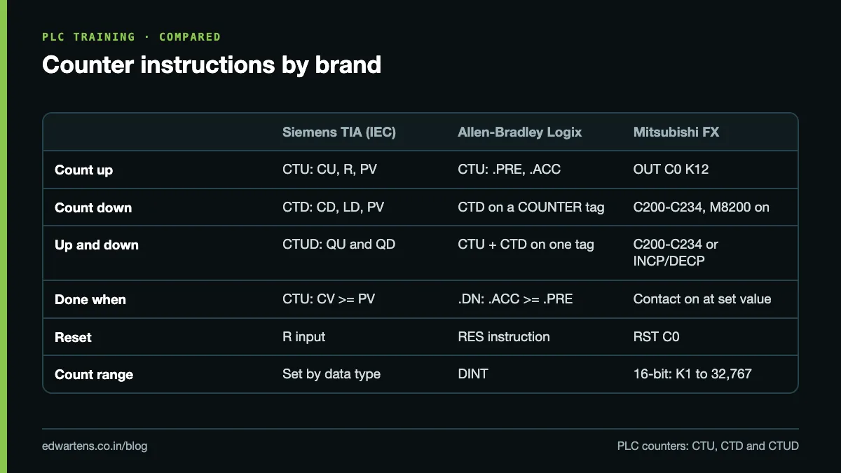
On the S7-1200 and S7-1500, CTU, CTD and CTUD are function blocks. Each call needs an instance: a single-instance data block that TIA Portal offers to create when you drop the instruction, or a multi-instance inside your own FB. The counter's data type is selectable (Int by default, so up to 32,767; DInt for larger counts). In SCL a call looks like this:
"C_Bottles"(CU := "PE_Bottle",
            R  := "Crate_Reset",
            PV := 12,
            Q  => "Batch_Done",
            CV => "Bottle_Count");
Siemens S7-300/400: legacy S5 counters
Older STEP 7 programs use S_CU, S_CD and S_CUD (or the CU, CD and SC coils) on counter addresses C0, C1 and so on. They behave differently from IEC counters, and the difference causes real bugs during migration:
- The count range is 0 to 999, and the value is available in binary (CV) and BCD (CV_BCD).
- A rising edge on S loads the value at PV, written as a constant like
C#12. - Q is 1 whenever the count is greater than zero, not when a preset is reached. To detect "12 reached", compare CV with 12.
The S7-1200 does not support these legacy counters, so converted code must use the IEC versions.
Allen-Bradley Studio 5000
A counter is a tag of type COUNTER with members .PRE, .ACC (both DINT), .CU, .CD, .DN, .OV and .UN. The instructions are CTU(Counter, Preset, Accum) and CTD(...), and RES clears the counter:
XIC PE_Bottle         CTU C_Bottles 12 0
XIC Crate_Reset       RES C_Bottles
XIC C_Bottles.DN      OTE Batch_Done
The accumulated value is kept when the rung goes false and through a power cycle; only RES or a move into .ACC changes it. Up/down counting in ladder uses a CTU and a CTD on the same COUNTER tag; a CTUD instruction exists in function block diagram and Structured Text. On SLC 500 and MicroLogix, counters are C5:0 and so on, with a 16-bit .ACC.
Mitsubishi FX (GX Works2)
Counters are devices C0, C1 and so on, with the preset written as a K constant or a D register:
LD   X002
OUT  C0  K12
LD   X004
RST  C0
LD   C0
OUT  Y001
On the FX3U (and FX2N), C0 to C99 are general 16-bit up counters, C100 to C199 are latched (keep their value at power off), C200 to C234 are 32-bit up/down counters whose direction is set by special relays M8200 to M8234 (on = count down), and C235 to C255 are the high-speed counters. A 16-bit counter stops at its set value; it does not count past it. The counter must be reset with RST before it counts again.
The scan-time limit
A normal counter is executed in the program scan. To see one pulse it must see the input on in one scan and off in a later one. So each pulse must be on for at least one full scan and off for at least one full scan, which gives a theoretical maximum of:
Maximum count rate = 1 / (2 x scan time)
| Scan time | Theoretical maximum | Safe working figure (half) |
|---|---|---|
| 2 ms | 250 pulses/s | about 125 pulses/s |
| 5 ms | 100 pulses/s | about 50 pulses/s |
| 10 ms | 50 pulses/s | about 25 pulses/s |
| 20 ms | 25 pulses/s | about 12 pulses/s |
Scan time varies, so design to about half. The input filter adds a second limit: the S7-1200's digital inputs filter at 6.4 ms by default, so a pulse shorter than that never reaches the program at all. Reduce the filter in the device configuration if your pulses are short, and accept that this also makes the input more sensitive to noise.
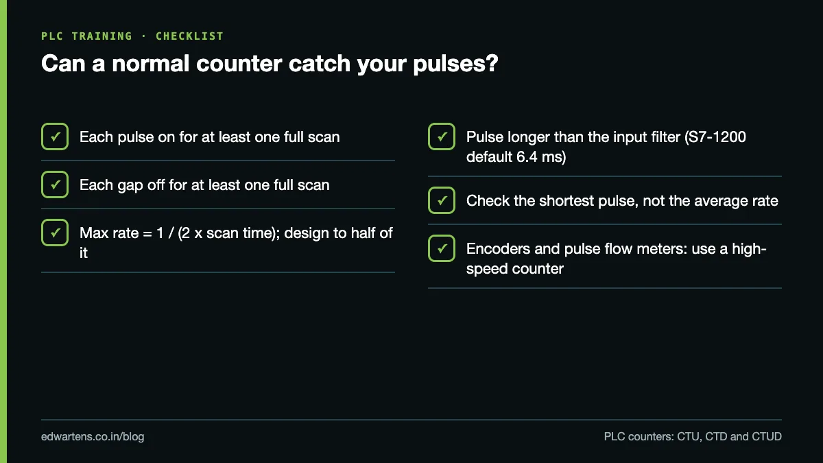
What matters is the shortest on-time and off-time, not the average rate. A bottle line at 600 bottles per minute is only 10 per second, but if each bottle blocks the photo-eye for 15 ms and your scan is 10 ms, you are at the edge. An encoder with 1,000 pulses per revolution on a shaft at 1,500 rpm produces 25,000 pulses per second, which is far beyond any scan-based counter.
When to use a high-speed counter (HSC): encoders, flow meters with pulse outputs, fast product counting, and anything whose pulses are shorter than about two scans. An HSC counts in hardware, independent of the scan. The S7-1200 has built-in HSCs on designated onboard inputs (up to 100 kHz on the fastest, depending on CPU), configured in the device configuration and read through the HSC instruction or its input address. The Mitsubishi FX3U uses C235 to C255 on X000 onwards. Allen-Bradley Micro800 controllers have built-in HSCs, and CompactLogix uses an HSC module such as the 1769-HSC.
Worked example 1: bottle batching
Task: fill crates with 12 bottles each. A photo-eye at the crate entry counts bottles. At 12, stop the bottle conveyor and run the crate conveyor until a new empty crate arrives, then reset and start again.
| Address | Tag | Use |
|---|---|---|
| I0.2 | PE_BOTTLE | Bottle photo-eye at crate entry |
| I0.4 | CRATE_PE | 1 when a crate is in position |
| M20.0 | BATCH_DONE | Counter Q |
| M20.2 | CRATE_RESET | One-scan reset pulse |
| Q0.0 | BOTTLE_CONV | Bottle conveyor |
| Q0.1 | CRATE_CONV | Crate conveyor |
|--[P I0.4 CRATE_PE / M20.1 ]--[ M20.0 BATCH_DONE ]--( M20.2 CRATE_RESET )--|
|--[ I0.2 PE_BOTTLE ]--[ CTU C_BOTTLES  R=M20.2  PV=12  Q=>M20.0 ]--|
|--[ M10.0 RUN ]--[/ M20.0 BATCH_DONE ]--( Q0.0 BOTTLE_CONV )--|
|--[ M20.0 BATCH_DONE ]--( Q0.1 CRATE_CONV )--|
How it runs: the 12th bottle sets BATCH_DONE, the bottle conveyor stops and the crate conveyor starts. The full crate leaves (CRATE_PE goes to 0), the empty one arrives (CRATE_PE rises), the reset pulse clears the counter, the crate conveyor stops and bottles flow again. The reset uses a rising edge, so a crate that sits on the sensor does not hold the counter at zero.
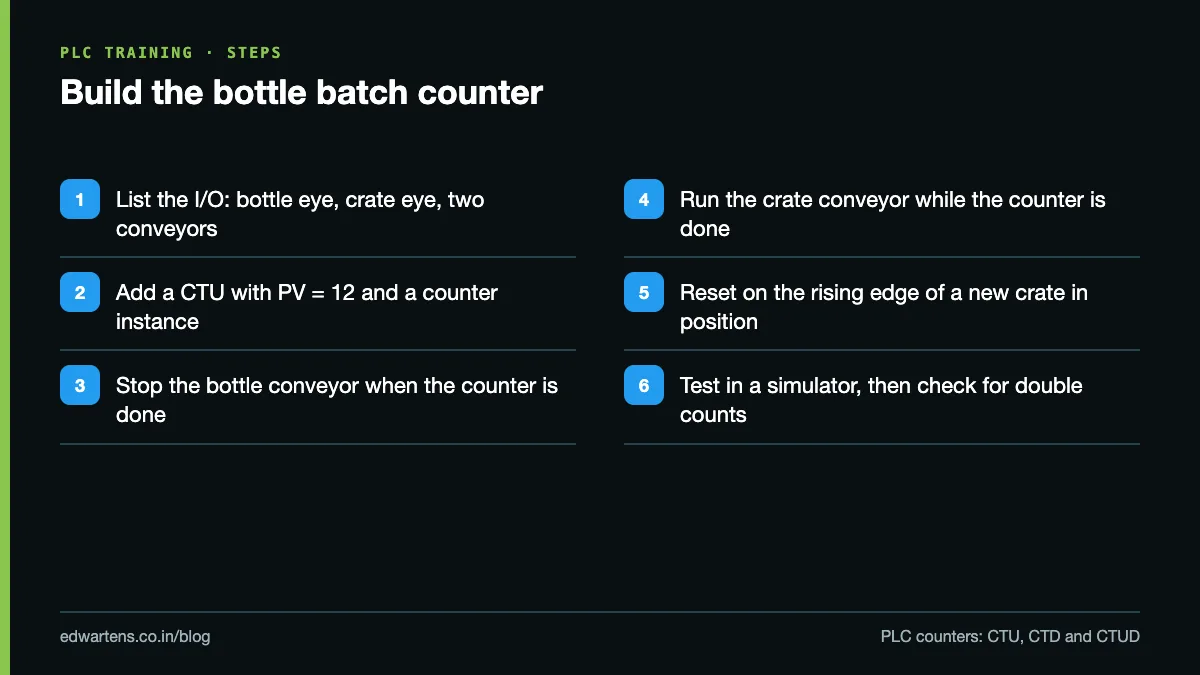
Mount the photo-eye where bottles are separated, or two touching bottles read as one. If crates arrive nose to tail, CRATE_PE never drops; position the sensor where there is always a gap.
Worked example 2: parts counter with reset (a buffer between two machines)
Task: a buffer conveyor holds up to 20 parts between a press and a welder. A sensor at the entry counts parts in, a sensor at the exit counts parts out. Stop the press when the buffer is full and stop the welder when it is empty. The operator can reset the count after clearing the buffer by hand.
"C_Buffer"(CU := "PE_In",
           CD := "PE_Out",
           R  := "Reset_PB",
           LD := FALSE,
           PV := 20,
           QU => "Buffer_Full",
           QD => "Buffer_Empty",
           CV => "Parts_In_Buffer");
Then two rungs: the press runs only with [/ Buffer_Full ] in its permissive, and the welder's infeed only with [/ Buffer_Empty ]. Parts_In_Buffer goes to the HMI.
In Studio 5000, put CTU C_Buffer 20 0 on PE_In and CTD C_Buffer 20 0 on PE_Out (same tag), and use GEQ C_Buffer.ACC 20 for full and LEQ C_Buffer.ACC 0 for empty. In GX Works2 it is simpler to use INCP D0 and DECP D0 on the two sensors and compare D0 than to drive a C200-range counter's direction relay from two inputs.
The weakness of every up/down count: one missed or doubled pulse makes the count wrong for ever. The operator reset is the minimum fix. Better, add an "empty" sensor at the bottom of the buffer and reset the counter automatically whenever it confirms the buffer is empty.
Common mistakes
- Counting with ADD on a raw input, which counts every scan. Use a counter.
- Holding R (or RES) on permanently, so the counter never counts.
- Assuming the S5 counter's Q means "preset reached". It means "count above zero".
- Forgetting that Allen-Bradley counters keep .ACC through power cycles, so a batch resumes mid-count after a power cut.
- Using a normal counter on an encoder. Check pulse width against scan time.
For timers, the counterpart to this article, read TON, TOF and TONR explained. For counters inside complete programs, see 20 PLC ladder logic examples with solutions.
Learn it free
Counters, timers and high-speed counting are covered with simulator practice in the free Siemens TIA Portal, Allen-Bradley Studio 5000 and Mitsubishi FX with GX Works2 courses. Each has written notes, practice tasks and a 15-question final assessment, and learning is free with an account.
Frequently asked questions
Q: What is the difference between CTU and CTD?
A: CTU adds 1 to the count on each rising edge of its input and signals done when the count reaches the preset. CTD subtracts 1 per edge; on IEC counters it signals when the count reaches zero or below.
Q: What do .ACC, .PRE and .DN mean on an Allen-Bradley counter?
A: .PRE is the preset target, .ACC is the accumulated count, and .DN is the done bit, set when .ACC is greater than or equal to .PRE. RES clears .ACC and the status bits.
Q: Why does my counter miss pulses?
A: Each pulse must be on for at least one scan and off for at least one scan, and longer than the input filter time. If the pulses are shorter, use a high-speed counter.
Q: How fast can a normal PLC counter count?
A: In theory up to 1 divided by twice the scan time, so about 50 pulses per second at a 10 ms scan. Design to about half that, and use a high-speed counter beyond it.
Q: Does a PLC counter keep its value after power off?
A: It depends. Allen-Bradley counters keep .ACC, Mitsubishi C100 to C199 are latched while C0 to C99 are not, and a Siemens IEC counter keeps its value only if its instance data is set as retentive.
Learn this, free
The courses that teach this
Every lesson, the written notes and the practice are free with an account. Only the certificate is optional and paid.