20 PLC ladder logic examples with solutions
The short answer
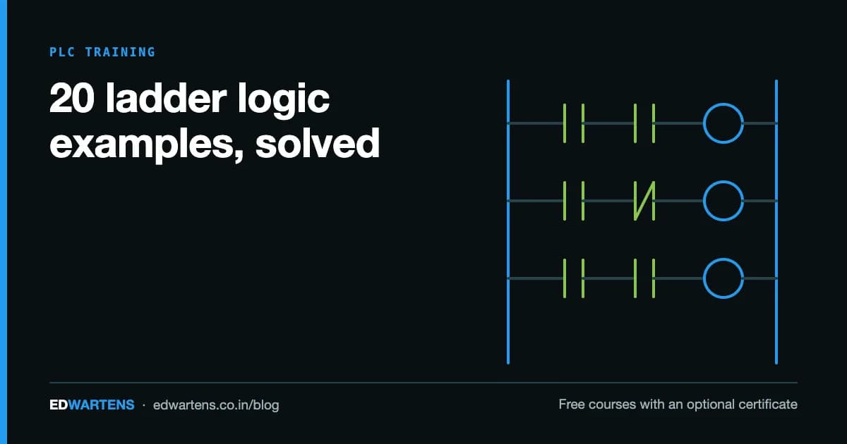
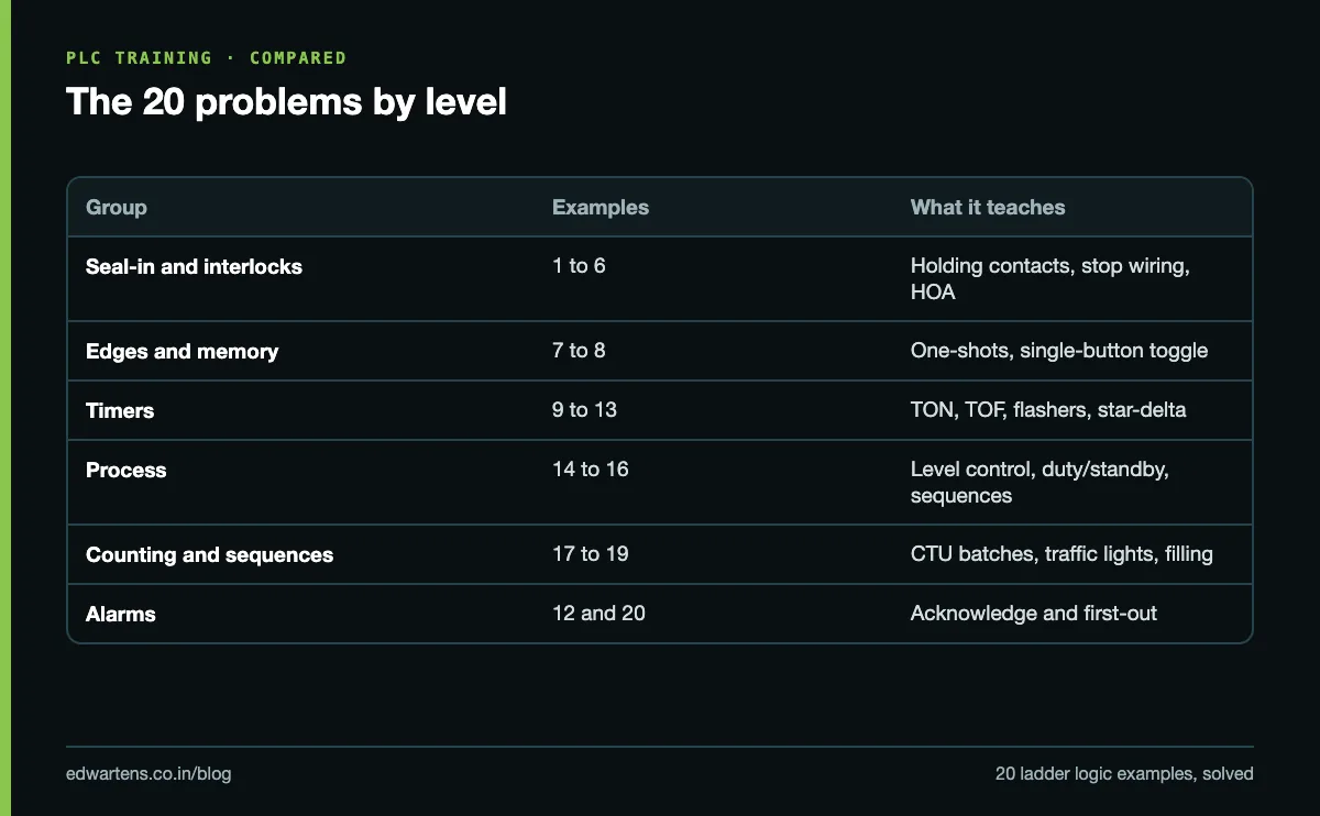
The 20 problems below cover nearly every pattern a PLC interview, viva or first commissioning job tests: seal-in, interlocks, edges, timers, counters, sequences and alarms. Each one has the problem, an I/O list, the solution rung by rung in a text ladder notation, and the mistake that most often breaks it. Addresses are Siemens S7-1200 style (I0.0, Q0.0, M10.0) with IEC timers and counters; the same logic runs on Allen-Bradley, Mitsubishi, Delta or OpenPLC with only the addresses changed.
How to read the rungs
Each rung is written left to right between the two power rails. A + marks where a parallel branch leaves and rejoins the main line.
| Text notation | Meaning | Siemens LAD | Allen-Bradley |
|---|---|---|---|
[ X ] | Normally open contact, true when X is 1 | NO contact | XIC |
[/ X ] | Normally closed contact, true when X is 0 | NC contact | XIO |
( Y ) | Output coil, follows the rung | Coil | OTE |
(S Y) / (R Y) | Set (latch) and reset (unlatch) | S and R coils | OTL and OTU |
[P X / M] | True for one scan when X goes 0 to 1, M stores the old state | P contact or R_TRIG | ONS after the condition |
[N X / M] | True for one scan when X goes 1 to 0 | N contact or F_TRIG | OSF |
One wiring rule applies to every motor example. The stop button and the overload relay contact (95-96) are wired as normally closed contacts to their inputs, so the input reads 1 when healthy. In the program you therefore examine them with a normally open contact, [ I0.1 STOP ]. A broken wire then stops the machine instead of silently disabling the stop button. The seal-in circuit article explains this in more depth. The emergency stop is never only a PLC input: it must cut the contactor coils in hardware as well.
Common I/O for the motor examples:
| Address | Tag | Field device |
|---|---|---|
| I0.0 | START | Start push button, NO |
| I0.1 | STOP | Stop push button, NC |
| I0.2 | OL | Overload relay contact 95-96, NC |
| Q0.0 | MOTOR | Contactor coil KM1 |
Basics: seal-in, interlocks and modes
1. Start/stop with seal-in
Problem: press START and the motor runs and keeps running after the button is released. STOP or an overload trip stops it.
|--+--[ I0.0 START ]--+--[ I0.1 STOP ]--[ I0.2 OL ]--( Q0.0 MOTOR )--|
|  |                  |
|  +--[ Q0.0 MOTOR ]--+
The Q0.0 contact in parallel with START is the seal-in (holding) contact. Once the coil is on, it keeps its own rung true.
Common mistake: writing [/ I0.1 STOP ] for an NC-wired stop button. The input is 1 at rest, the NC contact is false, and the motor never starts.
2. Start and stop from two locations
I/O: START1 I0.0 and START2 I0.3 (NO), STOP1 I0.1 and STOP2 I0.4 (NC), OL I0.2, MOTOR Q0.0.
|--+--[ I0.0 START1 ]--+--[ I0.1 STOP1 ]--[ I0.4 STOP2 ]--[ I0.2 OL ]--( Q0.0 MOTOR )--|
|  +--[ I0.3 START2 ]--+
|  +--[ Q0.0 MOTOR  ]--+
Starts go in parallel, stops go in series. Any start can start it; any stop can stop it.
Common mistake: putting the two stops in parallel. Then pressing one stop alone does nothing, because the other branch still carries the rung.
3. Set/reset latch with stop priority
Problem: the same motor using latch and unlatch coils instead of a seal-in.
|--[ I0.0 START ]---------------------------( S Q0.0 MOTOR )--|
|--+--[/ I0.1 STOP ]--+---------------------( R Q0.0 MOTOR )--|
|  +--[/ I0.2 OL ]----+
Here [/ ] is correct: the NC stop input drops to 0 when pressed (or when its wire breaks), the NC contact goes true and the reset fires. The reset rung sits after the set rung, so if both are true in the same scan the reset is written last and wins. In TIA Portal's box instructions the dominant input carries the 1: SR (R1) gives reset priority, RS (S1) gives set priority.
Common mistake: latching a motor that must not restart by itself. On Allen-Bradley, an OTL bit keeps its state through a power cycle and the prescan does not clear it, so the motor can restart when power returns. On Siemens, a set M bit survives a restart if it is marked retentive. Use seal-in for motors and keep latches for remembering events.
4. Jog and run
I/O: as example 1, plus JOG I0.3 (NO) and an internal RUN bit M10.0.
|--+--[ I0.0 START ]--+--[ I0.1 STOP ]--[ I0.2 OL ]--( M10.0 RUN )--|
|  +--[ M10.0 RUN ]---+

|--+--[ M10.0 RUN ]----------------+--[ I0.1 STOP ]--[ I0.2 OL ]--( Q0.0 MOTOR )--|
|  +--[ I0.3 JOG ]--[/ M10.0 RUN ]-+
RUN seals itself; JOG drives the motor only while held.
Common mistake: sealing on Q0.0. Jog energises Q0.0, Q0.0 seals the rung, and the "jog" becomes a run that will not stop when the button is released.
5. Forward/reverse with interlock
I/O: FWD I0.0, REV I0.3 (NO), STOP I0.1, OL I0.2, KM_F Q0.0, KM_R Q0.1.
|--+--[ I0.0 FWD ]--+--[ I0.1 STOP ]--[ I0.2 OL ]--[/ Q0.1 KM_R ]--( Q0.0 KM_F )--|
|  +--[ Q0.0 KM_F ]-+

|--+--[ I0.3 REV ]--+--[ I0.1 STOP ]--[ I0.2 OL ]--[/ Q0.0 KM_F ]--( Q0.1 KM_R )--|
|  +--[ Q0.1 KM_R ]-+
Each direction's rung contains an NC contact of the other output. Pressing REV while running forward does nothing; the operator must press STOP first. If both buttons arrive in the same scan, the first rung wins and the second sees Q0.0 already on.
Common mistake: relying on the software interlock alone. A welded contactor or a forced output bypasses it and shorts two phases. Wire an NC auxiliary contact of each contactor into the other's coil circuit, and use a mechanical interlock where the contactor maker offers one.
6. Hand-Off-Auto selector
I/O: HAND I0.3 and AUTO I0.4 (selector positions; OFF makes neither), DEMAND M10.1 from the auto logic, OL I0.2, PUMP Q0.0.
|--+--[ I0.3 HAND ]-------------------+--[ I0.2 OL ]--( Q0.0 PUMP )--|
|  +--[ I0.4 AUTO ]--[ M10.1 DEMAND ]-+
Common mistake: putting the protection inside the AUTO branch only. Overload, guards and dry-run protection must sit after the branch so that HAND respects them too.
Edges and memory
7. One-shot: one action per press
Problem: each press of INC (I0.5) adds 1 to a batch size in MW20.
|--[P I0.5 INC / M10.2 ]--( M10.3 INC_PULSE )--|
|--[ M10.3 INC_PULSE ]--[ ADD MW20 + 1 => MW20 ]--|
In Studio 5000 the first rung is XIC INC ONS INC_ONS OTE INC_PULSE.
Common mistake: leaving out the edge. ADD then runs every scan the button is held: a 200 ms press on a 5 ms scan adds about 40, not 1. A second mistake is reusing one edge memory bit for two different edges; each needs its own.
8. One push button toggles a light
I/O: PB I0.6 (NO), LAMP Q0.2.
|--[P I0.6 PB / M10.4 ]--( M10.5 PB_PULSE )--|

|--+--[ M10.5 PB_PULSE ]--[/ Q0.2 LAMP ]--+--( Q0.2 LAMP )--|
|  +--[/ M10.5 PB_PULSE ]--[ Q0.2 LAMP ]--+
The second rung is an exclusive-OR: on the pulse scan the lamp inverts, on every other scan it holds.
Common mistake: toggling on the raw input. The lamp flips every scan while the button is held and ends in a random state.
Timers
The timer article covers TON, TOF and TONR in full. In the rungs below, [ TON T_X PT=T#5s ] is an IEC timer whose instance is T_X, and T_X.Q is its done output.
9. Warning horn before a conveyor starts
I/O: START, STOP, OL as before; HORN Q0.1, CONVEYOR Q0.0; RUN_REQ M10.6.
|--+--[ I0.0 START ]--+--[ I0.1 STOP ]--[ I0.2 OL ]--( M10.6 RUN_REQ )--|
|  +--[ M10.6 RUN_REQ ]-+

|--[ M10.6 RUN_REQ ]--[ TON T_WARN PT=T#5s ]--|
|--[ M10.6 RUN_REQ ]--[/ T_WARN.Q ]--( Q0.1 HORN )--|
|--[ T_WARN.Q ]--( Q0.0 CONVEYOR )--|
The horn sounds for 5 s, then the conveyor starts and the horn stops. STOP drops RUN_REQ, which resets the timer and stops the belt.
Common mistake: driving the conveyor from RUN_REQ and using the timer only for the horn, so the belt moves while the warning is still sounding.
10. Cooling fan that runs on after the motor stops
|--[ Q0.0 MOTOR ]--[ TOF T_FAN PT=T#2m ]--|
|--[ T_FAN.Q ]--( Q0.5 FAN )--|
The fan starts with the motor and runs for 2 minutes after it stops.
Common mistake: building this from a TON on [/ Q0.0 ]. The fan then also runs for the first 2 minutes after power-up, when the motor has never run.
11. Flashing light
Option A, clock memory. In the S7-1200/1500 CPU properties, enable the clock memory byte (default MB0). Bit M0.5 then toggles at 1 Hz.
|--[ M10.7 ALARM ]--[ M0.5 CLOCK_1HZ ]--( Q0.3 LAMP )--|
Option B, two timers (any PLC):
|--[ M10.7 ALARM ]--[/ T_ON.Q ]--[ TON T_OFF PT=T#500ms ]--|
|--[ T_OFF.Q ]--[ TON T_ON PT=T#500ms ]--|
|--[ M10.7 ALARM ]--[ T_OFF.Q ]--( Q0.3 LAMP )--|
T_OFF times the dark half; when it finishes, the lamp lights and T_ON times the lit half; T_ON then resets T_OFF and the cycle repeats.
Common mistake: enabling clock memory at MB0 and then using M0.x bits for your own logic. The CPU overwrites them every few milliseconds. That is why every internal bit in this article starts at M10.0.
12. Alarm with acknowledge
Problem: a new fault flashes the lamp and sounds a horn; ACK silences the horn and makes the lamp steady while the fault is still present; the lamp goes out when the fault clears.
I/O: FAULT I0.7 (1 = fault), ACK I1.5, LAMP Q0.3, HORN Q0.4, UNACK M11.4.
|--[P I0.7 FAULT / M11.5 ]-----------------( S M11.4 UNACK )--|
|--[ I1.5 ACK ]----------------------------( R M11.4 UNACK )--|

|--+--[ M11.4 UNACK ]--[ M0.5 CLOCK_1HZ ]--+--( Q0.3 LAMP )--|
|  +--[ I0.7 FAULT ]--[/ M11.4 UNACK ]-----+

|--[ M11.4 UNACK ]--( Q0.4 HORN )--|
Common mistake: setting UNACK on the level of the fault instead of its rising edge. ACK then cannot clear it while the fault is present, because the set rung writes it straight back.
13. Star-delta starter
I/O: START, STOP, OL as before; MAIN Q0.0 (KM1), STAR Q0.1 (KM3), DELTA Q0.2 (KM2); RUN M12.1.
|--+--[ I0.0 START ]--+--[ I0.1 STOP ]--[ I0.2 OL ]--( M12.1 RUN )--|
|  +--[ M12.1 RUN ]---+

|--[ M12.1 RUN ]--( Q0.0 MAIN )--|
|--[ M12.1 RUN ]--[ TON T_SD PT=T#8s ]--|
|--[ M12.1 RUN ]--[/ T_SD.Q ]--[/ Q0.2 DELTA ]--( Q0.1 STAR )--|
|--[ T_SD.Q ]--[ TON T_GAP PT=T#100ms ]--|
|--[ M12.1 RUN ]--[ T_GAP.Q ]--[/ Q0.1 STAR ]--( Q0.2 DELTA )--|
Main and star close together; after the star time the star contactor drops; after a short gap the delta contactor closes. Set the star time to how long the motor takes to run up in star (commonly 5 to 10 s) and keep the gap short, around 50 to 100 ms, so the motor does not slow down much before delta.
Common mistake: no changeover gap and no hardware interlock. Star and delta closed together is a phase-to-phase short circuit. Wire NC auxiliaries of KM2 and KM3 into each other's coils. The starter comparison explains when star-delta is the right choice at all.
Sequences, process and alarms
14. Tank fill with two level switches
I/O: LSL I1.0 (1 when liquid is at or above the low switch), LSH I1.1 (1 when at or above the high switch), OL I0.2, PUMP Q0.0.
|--+--[/ I1.0 LSL ]--+--[/ I1.1 LSH ]--[ I0.2 OL ]--( Q0.0 PUMP )--|
|  +--[ Q0.0 PUMP ]--+
This is example 1 with level switches for buttons: the pump starts when the level falls below LSL and seals in until LSH is reached. The gap between the switches is the hysteresis. For a sump being emptied, reverse it: start on high, stop on low.
Common mistake: using one switch for both start and stop, so the pump short-cycles on every ripple. Also: if the LSH wire breaks, the input reads 0 and the pump never stops. Fit an independent high-high switch that cuts the pump in hardware.
15. Duty/standby pumps that alternate
Problem: two sump pumps share the duty: the lead pump changes after every completed cycle, and if one pump trips the other takes over.
I/O: DEMAND M13.1 (from logic like example 14), P1_OK I1.2 and P2_OK I1.3 (1 = healthy), PUMP1 Q0.0, PUMP2 Q0.1, SEL M13.3 (0 = pump 1 leads).
|--[N M13.1 DEMAND / M13.2 ]--( M13.4 CYCLE_END )--|

|--+--[ M13.4 CYCLE_END ]--[/ M13.3 SEL ]--+--( M13.3 SEL )--|
|  +--[/ M13.4 CYCLE_END ]--[ M13.3 SEL ]--+

|--[ M13.1 DEMAND ]--+--[/ M13.3 SEL ]---+--[ I1.2 P1_OK ]--( Q0.0 PUMP1 )--|
|                    +--[/ I1.3 P2_OK ]--+

|--[ M13.1 DEMAND ]--+--[ M13.3 SEL ]----+--[ I1.3 P2_OK ]--( Q0.1 PUMP2 )--|
|                    +--[/ I1.2 P1_OK ]--+
The falling edge of DEMAND toggles SEL (the toggle from example 8). Each pump runs if it is the lead, or if the other pump is faulted.
Common mistake: alternating on every scan or on the level instead of the edge, so both pumps run in turn within one cycle, or the lead changes randomly.
16. Sequential start of three conveyors
Problem: start the discharge conveyor CV3 first, then CV2 after 3 s, then the feed conveyor CV1 after another 3 s, so material never lands on a stopped belt.
|--+--[ I0.0 START ]--+--[ I0.1 STOP ]--[ I0.2 OL ]--( M14.2 RUN )--|
|  +--[ M14.2 RUN ]---+

|--[ M14.2 RUN ]--( Q0.2 CV3 )--|
|--[ Q0.2 CV3 ]--[ TON T_C2 PT=T#3s ]--|
|--[ M14.2 RUN ]--[ T_C2.Q ]--( Q0.1 CV2 )--|
|--[ Q0.1 CV2 ]--[ TON T_C1 PT=T#3s ]--|
|--[ M14.2 RUN ]--[ T_C1.Q ]--( Q0.0 CV1 )--|
Because each timer is enabled by the conveyor before it, losing CV3 stops everything upstream.
Common mistake: starting the feed first, which piles material at every transfer point. On a real plant, add running feedback from each motor (contactor auxiliary or speed switch) instead of trusting the output, and stop the feed first with off-delays so the downstream belts run empty.
17. Conveyor that stops after a batch
Problem: count 10 boxes past a photo-eye, stop the conveyor, and wait for RESET before the next batch.
I/O: START, STOP, OL; BOX_PE I0.3; RESET I0.4; CONVEYOR Q0.0; counter C_BOX.
|--+--[ I0.0 START ]--+--[ I0.1 STOP ]--[ I0.2 OL ]--[/ C_BOX.Q ]--( Q0.0 CONVEYOR )--|
|  +--[ Q0.0 CONVEYOR ]-+

|--[ I0.3 BOX_PE ]--[ CTU C_BOX  R=I0.4  PV=10 ]--|
The IEC CTU counts rising edges of its CU input, so no separate one-shot is needed. At 10, C_BOX.Q goes true, the conveyor stops and its seal-in drops. RESET clears the count; the operator then presses START.
Common mistake: counting with an ADD on the raw sensor (counts every scan), or a RESET button that sticks, which holds the counter at zero. The counters article covers CTU, CTD and CTUD across brands.
18. Traffic lights for a two-road junction
Problem: road A: red 10 s, green 8 s, amber 2 s, repeating. Road B: green 8 s then amber 2 s while A is red, and red otherwise.
|--[ M15.0 RUN ]--[/ T_AMB.Q ]--[ TON T_RED PT=T#10s ]--|
|--[ T_RED.Q ]--[ TON T_GRN PT=T#8s ]--|
|--[ T_GRN.Q ]--[ TON T_AMB PT=T#2s ]--|

|--[ M15.0 RUN ]--[/ T_RED.Q ]--( Q0.0 A_RED )--|
|--[ T_RED.Q ]--[/ T_GRN.Q ]--( Q0.1 A_GREEN )--|
|--[ T_GRN.Q ]--[/ T_AMB.Q ]--( Q0.2 A_AMBER )--|

|--[ Q0.0 A_RED ]--[ TON T_BG PT=T#8s ]--|
|--[ Q0.0 A_RED ]--[/ T_BG.Q ]--( Q0.3 B_GREEN )--|
|--[ Q0.0 A_RED ]--[ T_BG.Q ]--( Q0.4 B_AMBER )--|
|--[ M15.0 RUN ]--[/ Q0.0 A_RED ]--( Q0.5 B_RED )--|
The three road A timers form a chain. When T_AMB finishes, it removes T_RED's enable, every timer resets and the cycle starts again with A red. The lamps are dark for one scan at the changeover, a few milliseconds that nobody can see.
Common mistake: no all-red clearance. Here B goes green the instant A goes red. A real junction holds both roads red for a short interval between phases; add a timer for it as an exercise.
19. Bottle filling station
Problem: the conveyor runs until a bottle reaches the nozzle, stops, the valve opens for 4 s, then the conveyor moves the bottle out and brings the next one.
I/O: RUN M16.0, BOTTLE I0.3 (1 when a bottle is under the nozzle), CONVEYOR Q0.0, VALVE Q0.1, FILLED M16.1.
|--[ M16.0 RUN ]--[ I0.3 BOTTLE ]--[/ M16.1 FILLED ]--( Q0.1 VALVE )--|
|--[ Q0.1 VALVE ]--[ TON T_FILL PT=T#4s ]--|
|--[ T_FILL.Q ]--------------------------------( S M16.1 FILLED )--|
|--[/ I0.3 BOTTLE ]----------------------------( R M16.1 FILLED )--|

|--[ M16.0 RUN ]--+--[/ I0.3 BOTTLE ]--+--( Q0.0 CONVEYOR )--|
|                 +--[ M16.1 FILLED ]--+
FILLED remembers that this bottle is done, so the conveyor can move it while it still covers the sensor. FILLED clears when the sensor sees the gap.
Common mistake: no FILLED memory, so the full bottle sits under the nozzle and is filled again. Also note that stopping mid-fill resets the TON and the bottle gets a full 4 s more on restart; a TONR (retentive timer) fixes that.
20. First-out alarm
Problem: a compressor trips on any of three faults, and one fault often causes the others within milliseconds. The panel must show which fault came first.
I/O: F1 I1.0, F2 I1.1, F3 I1.2 (1 = fault), RESET I1.4, first-out bits FO1 to FO3 in M17.0 to M17.2, LAMP1 to LAMP3 Q1.0 to Q1.2.
|--[ I1.0 F1 ]--[/ M17.0 ]--[/ M17.1 ]--[/ M17.2 ]--( S M17.0 FO1 )--|
|--[ I1.1 F2 ]--[/ M17.0 ]--[/ M17.1 ]--[/ M17.2 ]--( S M17.1 FO2 )--|
|--[ I1.2 F3 ]--[/ M17.0 ]--[/ M17.1 ]--[/ M17.2 ]--( S M17.2 FO3 )--|

|--[ I1.4 RESET ]--[/ I1.0 ]--[/ I1.1 ]--[/ I1.2 ]--+--( R M17.0 )--|
|                                                   +--( R M17.1 )--|
|                                                   +--( R M17.2 )--|

|--+--[ M17.0 FO1 ]--[ M0.5 CLOCK_1HZ ]--+--( Q1.0 LAMP1 )--|
|  +--[ I1.0 F1 ]--[/ M17.0 FO1 ]--------+
Each set rung only fires if no first-out bit is set yet. The first-out lamp flashes; any other active fault shows steady. Repeat the lamp rung for faults 2 and 3.
Common mistake: a simple latch per fault, which tells you everything that tripped but not the order. If two faults arrive in the same scan, the lower-numbered one wins; for finer resolution than one scan you need time-stamped inputs. In practice trip inputs are often wired fail-safe (1 = healthy); then invert every fault contact.
The mistakes that break most of these
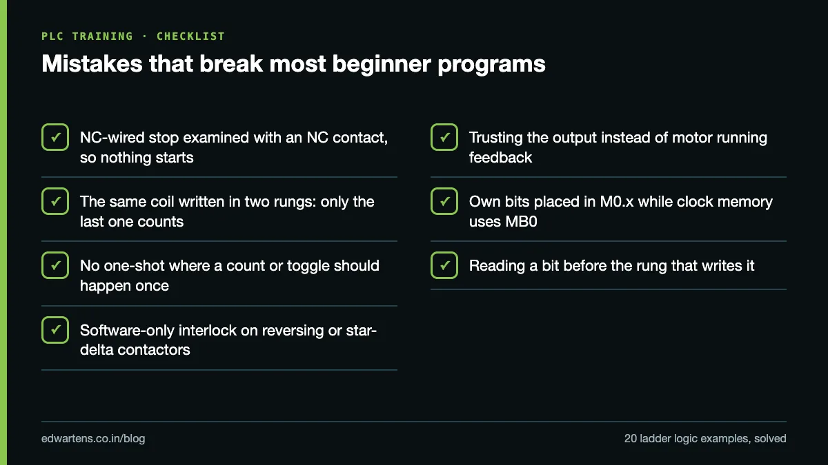
- Stop contact the wrong way round. Match the contact to the wiring: NC-wired stop, NO contact in a seal-in.
- Same coil written in two rungs. Only the last rung counts. Combine the conditions into one rung.
- No edge where a count or toggle is meant. Anything that should happen once per press needs a one-shot.
- Software-only interlocks. Reversing and star-delta contactors need hardware interlocks too.
- Trusting outputs instead of feedback. A contactor coil being on does not mean the motor is running.
- Clock memory clashes. If clock memory is on MB0, keep your own bits out of M0.x.
- Rung order. A bit read before the rung that writes it is one scan old. The scan cycle article shows why that matters.
How to practise these at home
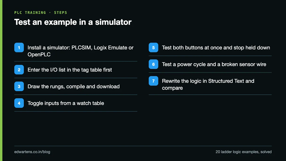
- Install a simulator: TIA Portal with PLCSIM, Studio 5000 Logix Emulate, GX Works2's built-in simulator, or OpenPLC, which is free. The free PLC software guide lists the options.
- Write the I/O list into the tag table before drawing any rung.
- Enter the rungs, compile and download to the simulated PLC.
- Force or toggle the inputs from a watch table and watch every output.
- Test the odd cases: both buttons together, stop held while start is pressed, power cycle mid-sequence, a sensor wire broken.
- Then rewrite the same logic in Structured Text. The Structured Text Generator gives you an IEC 61131-3 draft to compare against, and the PLC Code Explainer explains any rung you paste in and lists its risks.
Learn it free
Every example above is taught, with simulator practice, in the free courses. Start with Siemens TIA Portal for the S7-1200 addressing used here, Allen-Bradley Studio 5000 for the XIC/XIO/OTE version, or OpenPLC if you want to run them on an Arduino or Raspberry Pi. Learning is free with an account; the optional EDWartens certificate is the only paid item. For hands-on work with real PLCs, drives and panels, the classroom Automation Engineer Program runs at our Electronic City, Bangalore centre.
Frequently asked questions
Q: Should the stop button be a normally open or normally closed contact in ladder logic?
A: Wire the stop button normally closed, so the input is 1 when the button is not pressed, and examine it with a normally open contact in the seal-in rung. A broken wire then stops the machine instead of disabling the stop.
Q: What is the difference between a seal-in and a set/reset latch?
A: A seal-in holds itself only while its rung stays true, so it drops out on stop or power loss. A set/reset bit keeps its state until something resets it, and on some PLCs it survives a power cycle, which can restart a motor unexpectedly.
Q: Why does my counter count many times for one sensor pulse?
A: You are probably adding with a math instruction on the raw input, which executes every scan. Use a CTU, which counts rising edges, or put a one-shot in front of the ADD.
Q: Can these examples run on Allen-Bradley or Mitsubishi PLCs?
A: Yes. The logic is the same; only the addresses and instruction names change, for example XIC and XIO for contacts, OTL and OTU for set and reset, and ONS for the one-shot on Allen-Bradley.
Q: Is a PLC interlock enough for a forward/reverse starter?
A: No. Keep the software interlock, but also wire an NC auxiliary contact of each contactor into the other's coil circuit, and use a mechanical interlock where available, because a welded contact or a forced output defeats the program.
Learn this, free
The courses that teach this
Every lesson, the written notes and the practice are free with an account. Only the certificate is optional and paid.