PLC Program Structure: Siemens OB, FB and FC vs Rockwell Tasks, Programs and Routines

Structure is what separates a program from a pile of rungs
Anybody can write a rung. A maintainable program is organised so that a stranger finds the conveyor logic in a minute, the same valve behaves the same everywhere, and adding a fourth pump is a copy, not a rewrite. Siemens and Rockwell give you different building blocks for that.
Siemens: OB, FB, FC, DB
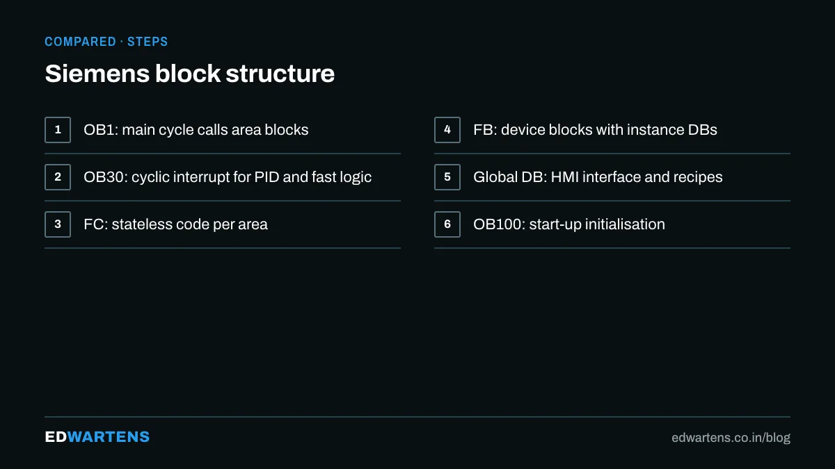
- Organisation blocks (OB): the entry points the operating system calls. OB1 is the main cycle; OB30 to OB38 are cyclic interrupts for PID and fast logic; OB100 runs at start-up; OB80s and OB120s handle errors.
- Function blocks (FB): code with memory. Each call has an instance data block holding its state. A valve FB, a motor FB, a PID.
- Functions (FC): code without memory; inputs to outputs, nothing remembered.
- Data blocks (DB): global data (recipes, HMI interface) or instance data.
A typical layout: OB1 calls a few FCs by area (infeed, filler, capper), each of which calls FB instances for the devices in that area, with a global DB for the HMI. The TIA Portal course and S7-1500 Advanced build exactly this.
Rockwell Logix: tasks, programs, routines, AOIs
- Tasks: continuous (the main scan), periodic (fixed rate, for PID and motion) and event tasks.
- Programs: inside a task, each with its own program-scoped tags and a main routine.
- Routines: the code units, in ladder, FBD, ST or SFC, called with JSR from the main routine.
- Add-On Instructions (AOI): reusable, instantiated blocks with their own backing tag, the equivalent of an FB.
- Controller-scoped tags and UDTs: global data and structures.
A typical layout: a continuous task with one program per machine area, a periodic task for PID, AOIs for valves, motors and drives, and UDTs for each device type. The Studio 5000 course and Studio 5000 Advanced do this.
What maps to what
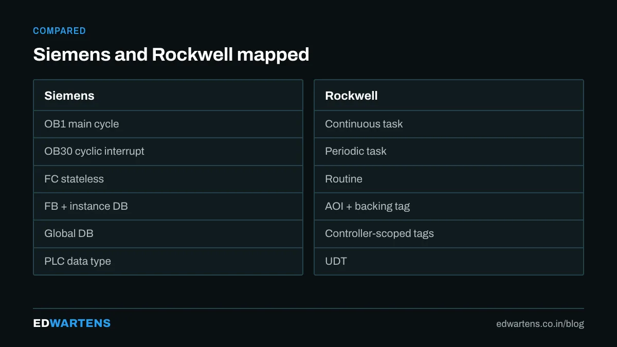
Siemens | Rockwell | Idea |
|---|---|---|
OB1 | Continuous task | Main scan |
OB30 cyclic interrupt | Periodic task | Fixed-rate execution |
FC | Routine (or AOI without state) | Stateless code |
FB with instance DB | AOI with backing tag | Stateful, reusable block |
Global DB | Controller-scoped tags | Shared data |
UDT (PLC data type) | UDT | Structures |
Multi-instance FB | AOI nested in AOI | Composition |
A layout that survives on both
- One block per device type (valve, motor, VFD, PID), fully tested, with a standard interface: command, feedback, mode, fault, alarm.
- One area block per machine section that instantiates devices and holds the sequence.
- One HMI interface structure that the SCADA reads, separated from the internal logic.
- Alarms handled in one place with a consistent structure.
- Fast logic (PID, encoders) in a periodic task or cyclic OB, never in the main scan.
- Comments on every block header: what it does, who wrote it, what changed.
The mistakes
- Everything in OB1 or the main routine, three thousand rungs long.
- FCs with static data faked through global memory.
- AOIs edited per instance instead of fixed once.
- No separation between HMI data and internal state, so a screen change breaks the logic.
If you would rather practise this on PLC training panels with an instructor, see our PLC course in Bangalore for the syllabus and duration.
Frequently asked questions
Can Rockwell do multi-instance like Siemens? Yes, an AOI can contain other AOIs.
Should I use FC or FB? FB whenever the block remembers anything (timers, edges, states). FC only for pure calculations.
Which structure do employers test? The interview question is usually "how would you structure a program for a machine with four stations"; the answer above works on both platforms.
Learn this, free
The courses that teach this
Every lesson, the written notes and the practice are free with an account. Only the certificate is optional and paid.


