PID Control in a PLC: How the Loop Works and How to Tune It Without Guessing

The loop in one sentence
A PID controller measures a process variable, compares it with a setpoint, and moves an output in proportion to the error, to the accumulated error, and to the rate of change of the error. Temperature, pressure, flow, level and speed loops all work this way, and a plant has hundreds of them.
The three terms, in plant language
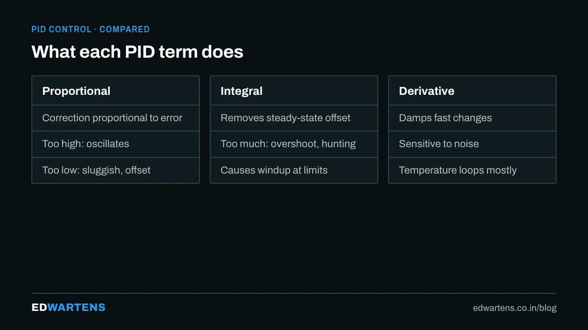
- Proportional (P): the bigger the error, the bigger the correction. High gain reacts strongly and oscillates; low gain is sluggish and leaves an offset.
- Integral (I): keeps pushing while any error remains, so the offset disappears. Too much integral and the loop overshoots and hunts; it also causes windup when the output is saturated.
- Derivative (D): reacts to how fast the error is changing, damping overshoot. Sensitive to noise; used on temperature, rarely on flow.
The output is a percentage that drives a valve, a VFD speed or a heater.
PID in the PLC
- Siemens TIA Portal: PID_Compact (single loop, built-in autotune), PID_3Step (motorised valves), PID_Temp. Called from a cyclic interrupt OB (OB30) at a fixed sample time, which matters: a PID in the main OB1 runs at a jittery rate. The PID Control course and the S7-1500 Advanced course configure it.
- Allen-Bradley Logix: the PID instruction (dependent or independent gains) and the PIDE function block with autotune, run in a periodic task.
- CODESYS and others: the standard PID function block from the utility library.
Parameters have different units: Siemens uses gain, integral time (s) and derivative time (s); Rockwell can use gain, reset (min per repeat) and rate (min). Converting badly is the classic mistake when moving tuning between brands.
A tuning procedure that works
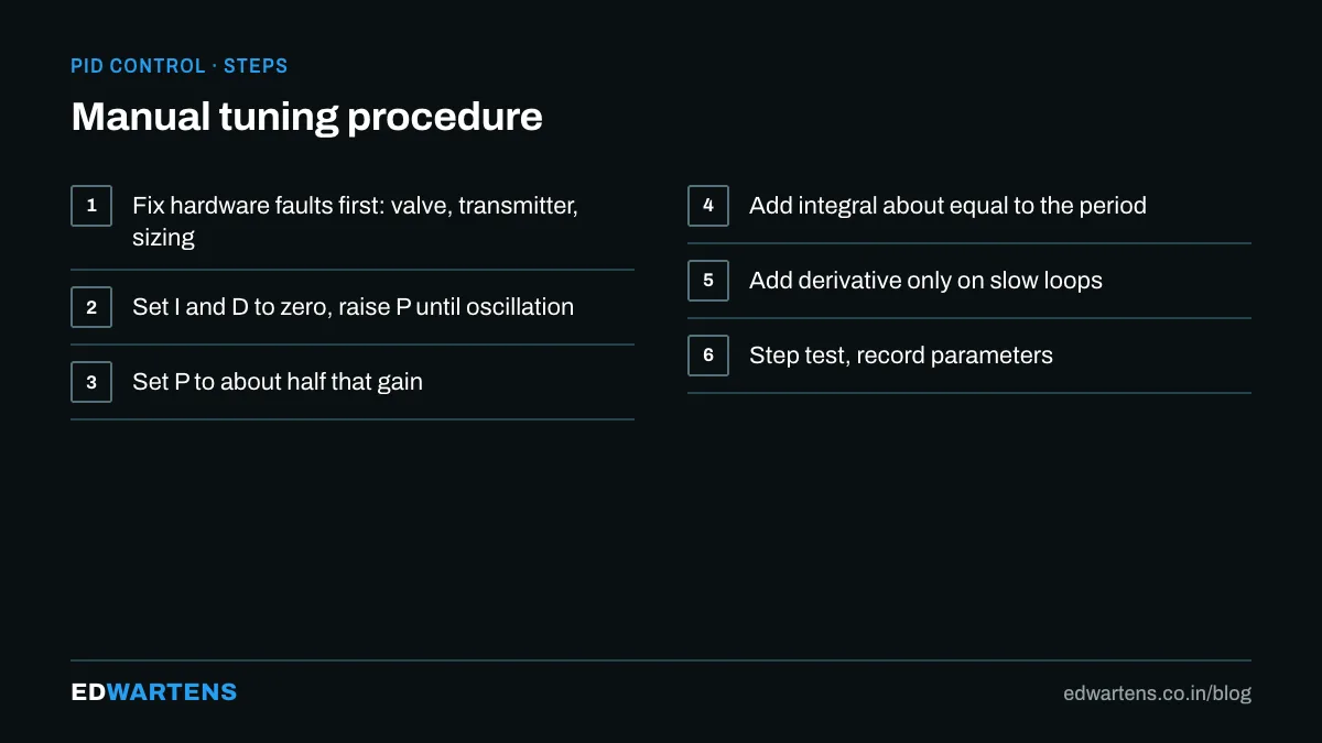
- Check the hardware first. A sticking valve, a noisy transmitter or a heater that is too small cannot be tuned away.
- Set I and D to zero. Raise P until the loop just starts to oscillate; note that gain (Ku) and the period (Pu).
- Back off. Set P to about half of Ku.
- Add integral. Integral time roughly equal to Pu; reduce until offset clears without hunting.
- Add derivative only if needed, about a quarter of the integral time, on slow loops.
- Step-test. Change the setpoint by 5 percent and watch: one overshoot of 10 to 15 percent and settle is good for most loops.
- Record the parameters in the loop sheet and the historian.
Autotune does steps 2 to 5 for you and works well on clean loops; it fails on noisy or non-linear ones, which is why you need the manual method.
Why loops oscillate
- Gain too high.
- Integral too aggressive.
- Valve stiction: the output moves, the valve does not, then jumps.
- Sample time too slow for a fast loop (flow needs 100 ms or better).
- Two loops fighting each other, such as pressure and flow on one line.
- Dead time: a long delay between output and measured effect, which no PID tunes well; use a slower loop or a Smith predictor.
Anti-windup and modes
Enable anti-windup or output limits so integral action stops accumulating when the valve is fully open. Provide manual, automatic and cascade modes on the HMI, with bumpless transfer, because an operator will need to take over.
Learning path
Theory with simulation in the MATLAB and Simulink course; PLC practice in the PID Control course; the instrument side in instrumentation basics; drives as the actuator in the VFD course.
If you want to learn this alongside PLCs, SCADA and drives in a classroom, see our industrial automation course in Bangalore.
Frequently asked questions
Do I need derivative? Usually not on flow and pressure; often on temperature.
What are typical starting values? For a temperature loop: gain 2 to 5, integral 100 to 300 s, derivative 0 to 30 s. Always tune from there.
Why does the loop work in simulation and not on the plant? Valve stiction, transmitter noise and dead time are not in the simulation.
Learn this, free
The courses that teach this
Every lesson, the written notes and the practice are free with an account. Only the certificate is optional and paid.


