Instrumentation Interview Questions and Answers for Freshers

The short answer
Most instrumentation interviews for freshers in India test the same core: why a 4 to 20 mA signal starts at 4 mA, how to turn a mA reading into a process value, how a DP transmitter measures level and flow, RTD versus thermocouple, which flow meter suits which fluid, what air to open means on a control valve, how an as-found and as-left calibration is done, and how to read an ISA-5.1 tag such as FIC-101. Add basic PID, hazardous area and SIS terms. Learn each answer with one worked number and one failure case, because the interviewer's next question is always "why?"
Watch: 4 to 20 mA transmitter wiring
The video above is Different Types of 4-20 mA Transmitter Wiring by Instrumentation Tools, embedded with thanks. EDWartens is not affiliated with the creator. It runs about 5 minutes and shows how 2-wire, 3-wire and 4-wire transmitters connect to a power supply and an analog input card, which is often the first question a fresher is asked. It is part of our free Industrial Instrumentation and Process Control course. The guide below adds the follow-up questions and the numbers you are expected to work out on paper.
How is an instrumentation interview for freshers usually run in India?
The format varies by employer, but most fresher hiring for instrumentation roles follows the same shape: a written or online test (aptitude plus basic technical multiple choice), one or two technical rounds, then an HR round. Campus drives and walk-ins both follow this pattern.
What the technical round stresses depends on who is hiring:
- EPC and design consultancies ask about P&IDs, instrument datasheets, hook-up drawings and tag numbering.
- System integrators ask about 4 to 20 mA wiring, PLC or DCS analog inputs, scaling and loop checks.
- Instrument manufacturers and their service partners ask about transmitter principles, calibration and HART.
- Plant maintenance in oil and gas, power, pharma, chemicals, cement and water asks about fault finding, calibration, control valves and, in oil and gas, hazardous areas and shutdown systems.
Expect to draw: a 2-wire loop with its power supply, a DP level hook-up on a tank, or a control valve with its positioner. Diploma holders applying for instrument technician roles get the same topics with more hands-on questions (which terminal goes where, how to connect a calibrator).
4 to 20 mA interview questions
Why 4 to 20 mA and not 0 to 20 mA? 4 mA is a "live zero": 0% of range reads 4 mA, so 0 mA means a fault such as a broken wire, a dead transmitter or a blown fuse. Fluke's explainer on the 4-20 mA current loop lists the live zero and noise resistance as the main reasons the signal is still the standard. The 4 mA floor also leaves enough current to run the electronics of a 2-wire transmitter.
Why current and not voltage? In a series loop the same current flows everywhere, so cable resistance does not change the reading as long as the supply has enough voltage left. A voltage signal drops along a long cable and picks up noise more easily.
What do readings below 4 mA or above 20 mA mean? Under the NAMUR NE 43 convention, normal measurement stays between 3.8 and 20.5 mA (slightly under or over range), while 3.6 mA or less, or 21 mA or more, signals a transmitter fault. Most smart transmitters let you choose upscale or downscale alarm.
What is the difference between 2-wire, 3-wire and 4-wire transmitters?
Type | How it is powered | Typical devices | What interviewers want to hear |
|---|---|---|---|
2-wire (loop powered) | 24 V DC on the same two wires that carry the signal | Pressure, DP and temperature transmitters | The transmitter is passive; the card or a separate supply powers the loop |
3-wire | Supply, signal and a shared common | Some small transmitters and sensors | Signal and supply share the 0 V return |
4-wire (self powered) | Separate supply, often 230 V AC or 24 V DC | Magnetic and Coriolis flowmeters, analysers | Output is active, so it goes to a passive analog input |
A classic trick question: connect an active (self powered) output to an active (loop powering) input card and the two supplies fight, so you read nothing sensible.
How do you check the loop has enough voltage? The supply must cover the transmitter's minimum terminal voltage plus every drop in the loop at 20 mA (or the alarm current). With a 24 V supply and a 250 ohm input resistor, the resistor alone drops 5 V at 20 mA, leaving 19 V for the cable, any barrier and the transmitter. Compare that with the minimum voltage in the transmitter datasheet. The 250 ohm resistor also gives 1 to 5 V across it, and it is the loop resistance a HART communicator typically needs to talk to the device.
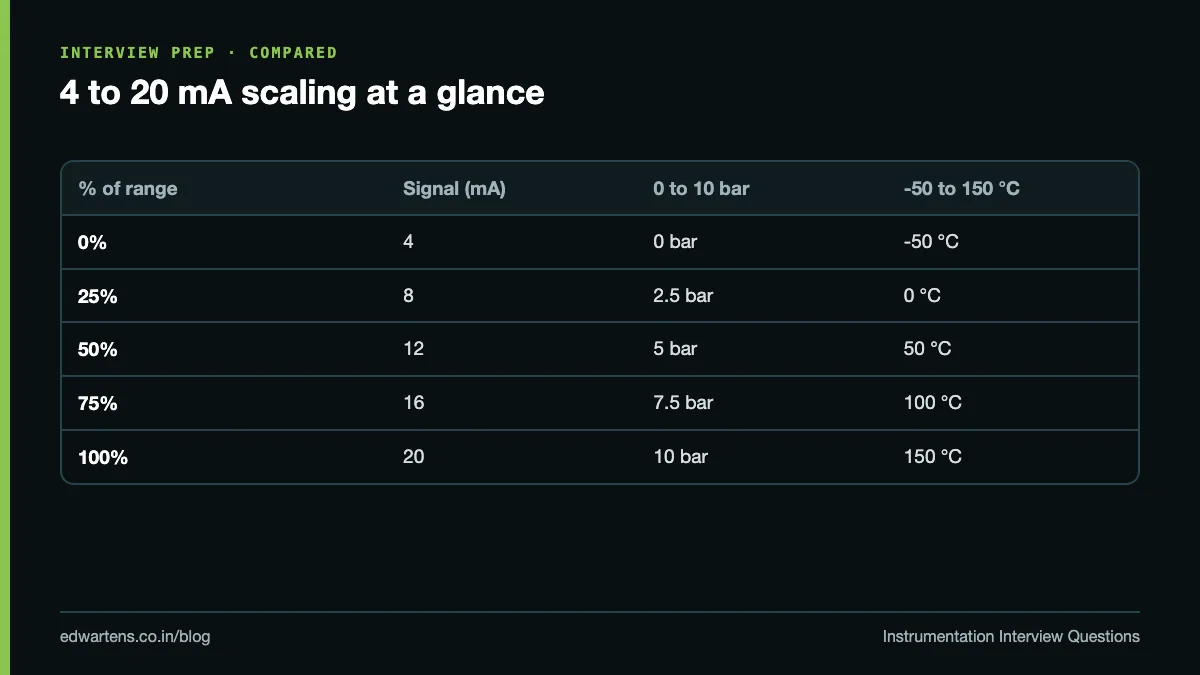
What is the scaling formula? Process value = LRV + (mA - 4) ÷ 16 × (URV - LRV), where LRV and URV are the lower and upper range values. Going the other way, mA = 4 + 16 × (PV - LRV) ÷ (URV - LRV).
Worked examples you should be able to do in your head:
- A 0 to 10 bar transmitter reads 9.6 mA: (9.6 - 4) ÷ 16 = 0.35, so the pressure is 3.5 bar.
- A -50 to 150 °C transmitter reads 8 mA: 25% of a 200 °C span is 50 °C, so the temperature is 0 °C.
- The same 0 to 10 bar transmitter at 7.5 bar: 4 + 16 × 0.75 = 16 mA.
In a Siemens S7-1200 or S7-1500, a 4 to 20 mA input appears as 0 to 27648 counts, which you scale with NORM_X and SCALE_X. Our post on the 4 to 20 mA formula for pressure, level and temperature has more worked cases.
Pressure and DP transmitter questions
Gauge, absolute and differential pressure? Gauge pressure is measured against atmosphere, absolute against a perfect vacuum, and differential is the difference between the transmitter's high (H) and low (L) ports.
How does a DP transmitter measure level in an open tank? It measures hydrostatic head: pressure = density × g × height. The H port connects near the tank bottom and the L port is vented to atmosphere. For water, 0 to 2 m of level is 0 to about 19.6 kPa (196 mbar). Because the reading depends on density, a change in liquid density changes the indicated level.
What about a closed, pressurised tank? The L port connects to the vapour space so the tank pressure cancels out. A dry leg (empty impulse line) works when the vapour does not condense. A wet leg (filled impulse line) is used when it does, as with steam. A full wet leg on the L side makes the DP negative: with a 2.5 m water wet leg and a 2 m level span, the range becomes about -24.5 kPa (empty) to -4.9 kPa (full). That is called zero elevation; a transmitter mounted below the bottom tap needs zero suppression instead.
Why is DP flow measurement square root? For an orifice or venturi, flow is proportional to the square root of DP. At 50% flow the DP is only 25% of range, so a linear transmitter output would read 8 mA, not 12 mA. Extract the square root once, either in the transmitter or in the DCS or PLC, never in both. A low-flow cut-off is used because the root amplifies noise near zero: 1% of DP already reads as 10% of flow.
How do you put a DP transmitter with a 3-valve manifold into service? With the equalising valve open, open the high side block valve, close the equalising valve, then open the low side block valve. Reverse the order to take it out. The aim is never to put full static pressure on one side of the sensor alone.
Temperature questions: RTD and thermocouple
What is a Pt100? A platinum RTD with 100 ohm at 0 °C whose resistance rises with temperature, about 0.385 ohm per °C, so it reads about 138.5 ohm at 100 °C. The resistance-temperature relationship and tolerance classes come from IEC 60751, currently the 2022 edition. Class A is ±(0.15 + 0.002 |t|) °C and Class B is ±(0.3 + 0.005 |t|) °C, so a Class B sensor at 100 °C is good to ±0.8 °C.
Why 3-wire RTDs? In a 2-wire connection the lead resistance adds to the reading. A 3-wire connection cancels it, assuming the leads are equal, which is why it is the plant standard. 4-wire removes lead effects completely and is used where accuracy matters most.
How does a thermocouple work? Two dissimilar metals joined at the hot end produce a small voltage that depends on the temperature difference between the hot (measuring) junction and the cold (reference) junction.
What is cold junction compensation? The transmitter measures the temperature of its own terminals and adds the matching millivolts, so the reading is referred to 0 °C. The cable from sensor to transmitter must be extension or compensating cable of the same type. Run copper from a junction box and the junction box becomes the cold junction, giving an error equal to its temperature difference.
Point | RTD (Pt100) | Thermocouple J | Thermocouple K |
|---|---|---|---|
Principle | Resistance changes with temperature | Voltage from iron and constantan junction | Voltage from nickel-chromium and nickel-aluminium junction |
Strength | Accuracy, stability, linearity | Cheap, works where iron is acceptable | Wide range, common in furnaces and boilers |
Weak point | Lower top temperature, slower, fragile | Iron oxidises at high temperature | Lower accuracy than RTD, drifts at high temperature |
Wiring | 3-wire copper cable | J extension or compensating cable | K extension or compensating cable |
Follow-ups: reversed thermocouple polarity reads low; an open thermocouple triggers burnout detection, which drives the output up or down. More detail is in our RTD, thermocouple and transmitter basics.
Flow meter questions: where each type fails
Interviewers rarely ask "how does a magnetic flowmeter work" alone. They ask "would you put one on diesel?" Know the failure cases.
Meter | Principle | Good for | Where it fails |
|---|---|---|---|
Orifice (DP) | Flow is proportional to the square root of DP across a plate | Clean liquids, gases, steam | Permanent pressure loss, needs straight pipe runs, limited turndown, worn plate edge, plugged taps |
Magnetic | A conductive liquid moving through a magnetic field generates a voltage proportional to velocity | Water, effluent, slurries, acids | Non-conductive fluids (oil, hydrocarbons, gas, demineralised water), part-full pipes, poor earthing |
Vortex | A bluff body sheds vortices at a frequency proportional to velocity | Steam, gases, clean low-viscosity liquids | Low flow, viscous fluids, pipe vibration, pulsating flow |
Coriolis | Flow twists vibrating tubes in proportion to mass flow; also gives density | Mass flow, dosing, custody transfer | Entrained gas, large line sizes (cost and weight), pressure drop |
Ultrasonic | Transit-time difference between upstream and downstream pulses | Large clean pipes, clamp-on retrofits | Bubbles or solids (transit-time), poor coupling, scaled or lined pipes |
So for diesel, a Coriolis meter is the safe answer; a magnetic flowmeter will not work because diesel does not conduct. For steam, vortex or DP. Straight runs are needed upstream of DP, vortex and ultrasonic meters because bends and valves distort the velocity profile. Our free Control Valves and Flow Measurement course covers sizing and selection.
Level measurement questions
- Radar: times a microwave echo from the surface. Non-contact and largely unaffected by vapour, pressure and temperature. Struggles with heavy foam, low dielectric liquids (weak echo) and false echoes from internal structures. Guided wave radar sends the pulse down a probe and handles low dielectric liquids and interfaces better.
- Ultrasonic: times a sound echo. Cheap, but the speed of sound changes with temperature and vapour, foam and dust absorb the pulse, it has a blocking distance near the sensor, and it cannot work in a vacuum.
- DP: hydrostatic head, as above. Simple and robust, but density dependent.
- Displacer: a float heavier than the liquid loses apparent weight as it is submerged (Archimedes), measured by a torque tube or spring. Good for interface level (oil over water) and high pressure vessels; errors when density changes, and mechanical parts wear.
Control valve questions
Air to open or air to close? An air to open valve closes when air or signal fails, so it is fail closed (FC). An air to close valve is fail open (FO). The choice is a safety decision: a fuel gas valve to a furnace is fail closed; cooling water to an exothermic reactor is fail open.
What does a positioner do? It compares the 4 to 20 mA command with the measured stem position and adjusts air to the actuator until they match, overcoming packing friction and process forces. An I/P converter only converts mA to air pressure (typically 3 to 15 psi, about 0.2 to 1.0 bar) and does not check where the valve actually went. Smart positioners with HART also give valve diagnostics.
What is Cv? The flow of water in US gallons per minute through the valve with a 1 psi pressure drop. Kv is the metric version (cubic metres per hour at 1 bar drop); Kv is about 0.865 × Cv. For liquids, flow = Cv × √(ΔP ÷ specific gravity).
Valve characteristics? Linear, equal percentage and quick opening. Equal percentage is common in process control because it compensates for pressure drop shifting away from the valve as flow rises.
Calibration questions
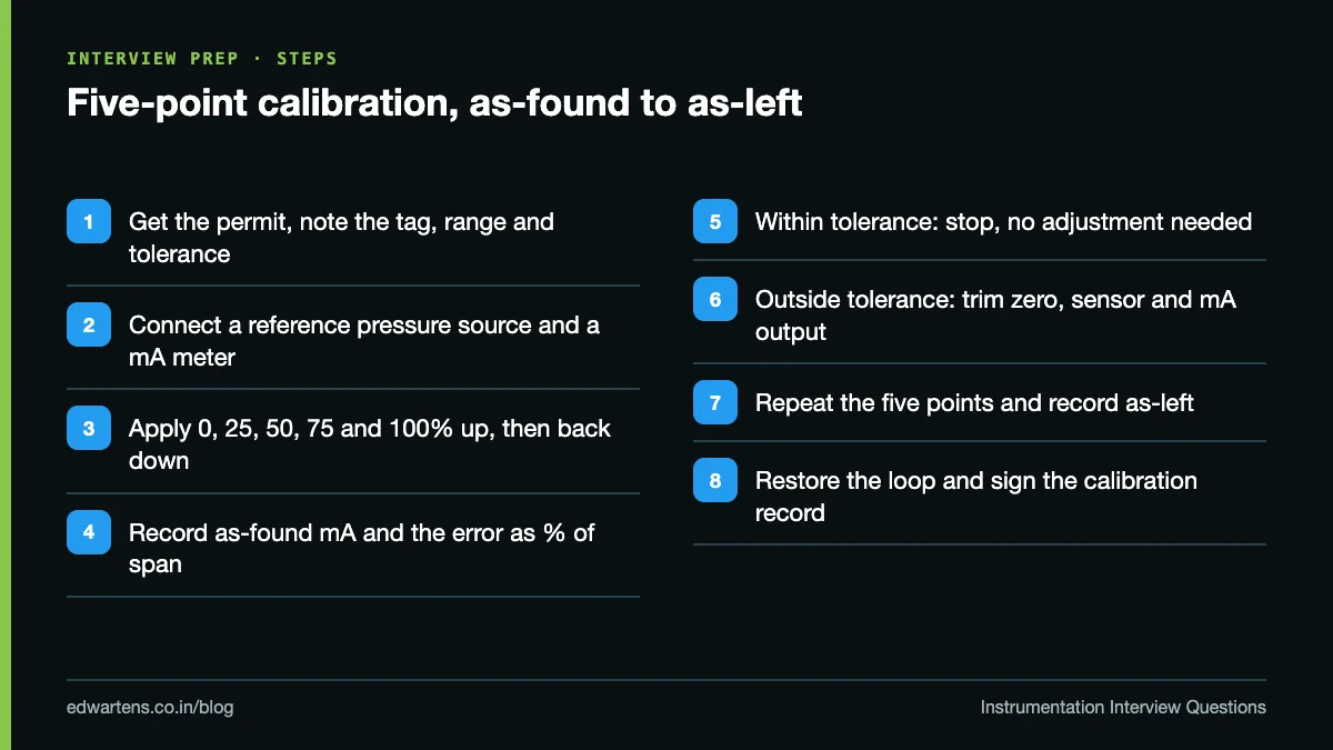
What are as-found and as-left? As-found is the reading recorded before you adjust anything; it shows whether the instrument was within tolerance while it was in service. As-left is recorded after adjustment. Fluke's HART pressure transmitter calibration procedure runs the As Found test against a tolerance, trims the pressure zero, mA output and input sensor only if needed, then documents the As-Left result.
How is a 5-point calibration done? Apply 0, 25, 50, 75 and 100% of range from a reference, record the output, and usually repeat going down to show hysteresis. Error as % of span = (measured mA - ideal mA) ÷ 16 × 100. At 50%, ideal 12.000 mA and measured 12.040 mA is a 0.25% of span error.
Re-ranging versus calibration? Changing the LRV and URV with a HART communicator is re-ranging; it needs no reference pressure and corrects nothing. Calibration compares the device with a more accurate reference. On a smart transmitter, a sensor trim corrects the digital reading and an analog output trim corrects the mA.
What is HART? A digital signal superimposed on the 4 to 20 mA loop using two tones (1,200 Hz for 1, 2,200 Hz for 0) that average to zero, so the analog value is undisturbed. It carries tag, range, the process value and diagnostics.
Our step-by-step pressure transmitter calibration guide and the free Instrument Calibration, Loop Checks and Commissioning course go further.
P&ID symbols and ISA-5.1 tag letters
Instrument tags and symbols follow ISA-5.1; the current edition is ANSI/ISA-5.1-2024. A tag is a set of letters plus a loop number. The first letter is the measured variable; the following letters say what the device does.
Letter | As first letter (measured variable) | As a following letter (function or modifier) |
|---|---|---|
A | Analysis | Alarm |
C | User's choice | Control |
E | Voltage | Primary element (sensor) |
F | Flow | Ratio, when used as a modifier |
I | Current | Indicate |
L | Level | Light, or low as a modifier |
P | Pressure | Point (test connection) |
S | Speed or frequency | Switch, or safety as a modifier |
T | Temperature | Transmit |
V | Vibration | Valve or damper |
Z | Position | Driver or actuator |
So PT-101 is a pressure transmitter, FIC-201 a flow indicating controller, LSHH-301 a level switch high high, PDT a differential pressure transmitter and PSV a pressure safety valve.
On the drawing, a plain circle is a field-mounted instrument, a circle with a solid line through it is in the main control room, a circle inside a square is a shared display such as a DCS, and a diamond inside a square is a PLC function. A dashed line is an electrical signal and a line with double cross-hatches is pneumatic. Practise on a real drawing with our guide to reading a P&ID and the free P&ID Reading and Instrumentation Design Documents course.
PID control questions
- P (proportional): output changes in proportion to error. Proportional band = 100 ÷ gain. P alone leaves a steady offset.
- I (integral): keeps changing the output while error exists, removing offset. Too much integral causes oscillation; integral windup happens when the output is saturated.
- D (derivative): reacts to the rate of change. It amplifies noise, so it is rarely used on flow or level and mostly on slow temperature loops. Flow loops are usually PI.
- Direct or reverse action: direct action increases output when the process value rises. A level controller driving an air to open outlet valve is direct acting.
- Cascade: a master controller (for example level) sets the set point of a faster slave controller (flow), so flow disturbances are corrected before they upset level.
Loop checking questions
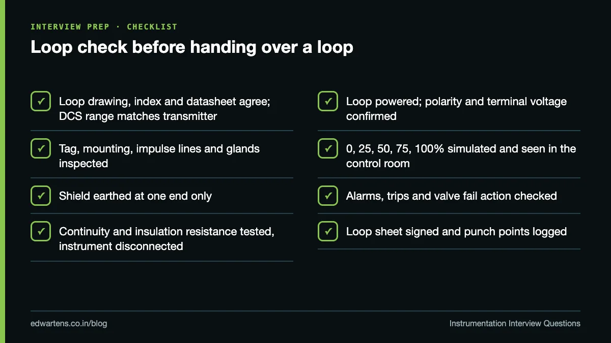
Cold loop versus hot loop check? A cold loop check verifies wiring, continuity and terminations without power. A hot loop check powers the loop and proves the signal from field device to control system display.
The usual sequence:
- Check the loop drawing, instrument index and datasheet; confirm the range in the DCS or PLC matches the transmitter.
- Inspect the installation: tag plate, mounting, impulse lines, cable glands, and shield earthed at one end only.
- Test continuity and insulation resistance with the instrument disconnected.
- Power the loop and confirm polarity and voltage at the transmitter terminals.
- Simulate 0, 25, 50, 75 and 100% with a calibrator or HART loop test and confirm the control room reading.
- Check alarms and interlock trips at their set points.
- For valves, stroke from the control system, confirm position feedback and limit switches, and confirm the fail action on loss of air and signal.
- Sign the loop sheet and log any punch points.
Typical fault-finding questions are covered in our 4 to 20 mA current loop troubleshooting guide.
Hazardous area questions
What are zones? For gas: Zone 0, an explosive atmosphere is present continuously or for long periods; Zone 1, likely in normal operation; Zone 2, not likely in normal operation and only briefly if it occurs. Dust uses Zones 20, 21 and 22. Area classification is done to IEC 60079-10-1 (third edition, 2020).
Ex d versus Ex i? Ex d (flameproof) lets an explosion happen inside the enclosure but contains it and cools escaping gases through flame paths. Ex i (intrinsic safety) limits energy so a spark or hot surface cannot ignite the gas; Ex ia suits Zone 0 and Ex ib Zone 1. Intrinsically safe loops use zener barriers (which need a dedicated IS earth) or galvanic isolators. You never open a live Ex d enclosure in a hazardous area without a permit.
Gas groups and temperature class? IIA, IIB and IIC, with IIC (hydrogen, acetylene) the most demanding. Temperature classes T1 to T6 cap surface temperature, with T6 the lowest at 85 °C. In Indian petroleum installations you will also hear about PESO approval for Ex equipment.
SIS questions
What is an SIS? A safety instrumented system, separate from the basic process control system (BPCS), that takes the plant to a safe state when a hazard limit is reached. Each safety instrumented function has a sensor, a logic solver and a final element such as a shutdown valve.
What is SIL? Safety integrity level, 1 to 4, a measure of the risk reduction a function must deliver; process plants mostly work at SIL 1 to 3 under the IEC 61511 series, the process sector application of IEC 61508.
What does 2oo3 mean? Two out of three sensors must agree to trip. 1oo2 is safer but trips spuriously more often; 2oo2 trips less often but is less safe; 2oo3 balances both and tolerates one failed sensor. SIS outputs are usually de-energise to trip, and every function needs periodic proof testing.
Instrumentation jobs for freshers: what the pay data says
On AmbitionBox, read 11 October 2026, the Instrument Engineer salary page (12.6k salaries) shows ₹3.5 to 3.9 lakh a year for 1 to 3 years of experience, rising to ₹4.6 to 5.1 lakh at 3 to 6 years. The Instrument Technician page (208 salaries) shows ₹3.3 to 3.7 lakh for 1 to 3 years, which AmbitionBox marks as its own estimate. These bands start at one year, so a day-one offer can be lower. If you are weighing the two careers, read instrumentation engineer vs automation engineer.
How to prepare in the weeks before the interview
- Make a one-page sheet: scaling formula, DP level formula, square root rule, Pt100 values, Cv definition, zone definitions.
- Practise drawing a 2-wire loop, a DP level hook-up with a wet leg and a valve with positioner, from memory.
- Pick ten tags from a real P&ID and expand each one aloud.
- For every instrument type, learn one case where it fails. That is what separates prepared freshers.
- Learn how the signal is used in a PLC, because many instrumentation jobs at integrators include PLC analog I/O. The free Instrumentation for PLC Engineers course bridges the two.
If you want hands-on time with PLCs, analog inputs and field devices, our PLC training for freshers explains what the first months of the classroom programme cover; the same programme runs as PLC training in Bangalore at our Electronic City centre. The EDWartens engineering team built the free instrumentation courses linked above to be useful whether or not you join.
Frequently asked questions
Q: What are the most asked instrumentation interview questions for freshers?
A: Why 4 to 20 mA has a live zero, mA to process value scaling, DP level and the DP flow square root, RTD versus thermocouple and cold junction compensation, flow meter selection, air to open versus air to close, and as-found and as-left calibration. P&ID tag letters from ISA-5.1 come up in almost every round.
Q: Is there an instrumentation interview questions and answers PDF?
A: You can save this page as a PDF from your browser's print menu. It is grouped by topic so you can revise one section at a time before the interview.
Q: What instrumentation interview questions are asked for oil and gas jobs?
A: Expect everything above plus hazardous area zones, Ex d and Ex i protection, gas groups and temperature classes, SIS voting such as 2oo3, shutdown valves and DP flow with orifice plates.
Q: Can a diploma holder get an instrument technician job as a fresher?
A: Instrument technician roles in plants, calibration labs and site commissioning are commonly open to diploma holders. The interview is more practical: wiring a loop, connecting a calibrator, reading a datasheet and basic safety.
Q: What is the difference between calibration and a loop check?
A: Calibration compares one instrument with a reference standard and adjusts it. A loop check proves the whole signal path, from field device through wiring to the control system display, alarms and interlocks.
Q: How are interview questions for experienced instrumentation engineers different?
A: They go deeper into project work: instrument sizing and datasheets, control valve sizing, SIS design and SIL verification, hazardous area design and commissioning problems you have personally solved.
Q: What is the salary of an instrumentation engineer fresher in India?
A: AmbitionBox, read 11 October 2026, shows ₹3.5 to 3.9 lakh a year for instrument engineers with 1 to 3 years of experience, based on 12.6k salaries. It shows no band for less than one year, so a first offer can be lower.
Learn this, free
The courses that teach this
Every lesson, the written notes and the practice are free with an account. Only the certificate is optional and paid.