4-20 mA Formula: Convert mA to Pressure, Level, Temp
The short answer
The 4-20 mA formula is PV = LRV + (I - 4) / 16 x (URV - LRV), where I is the loop current in mA, LRV is the value the transmitter is ranged to at 4 mA and URV the value at 20 mA. The reverse is I = 4 + 16 x (PV - LRV) / (URV - LRV). So 12 mA on a 0 to 10 bar transmitter is 5 bar, and 12 mA on a -50 to 150 °C transmitter is 50 °C, not 75 °C. A Siemens S7 analog input reports that same 12 mA as 13824 out of 27648.
If you just want the number, the free 4-20 mA Scaling Calculator does it in both directions and gives the raw PLC count. The rest of this page shows the working, so you can do it in an interview or on a loop sheet without a phone.
Four terms you need first
- LRV (lower range value): the process value at 4 mA. Often 0, but not always.
- URV (upper range value): the process value at 20 mA.
- Span: URV - LRV. A -50 to 150 °C transmitter has a span of 200 °C, not 150.
- Live zero: 4 mA, not 0 mA, means "bottom of range". A dead loop reads 0 mA, so a broken wire can never be mistaken for an empty tank.
The current span is always 16 mA (20 - 4). That gives one number worth memorising: every 1 mA is 6.25% of span. 8 mA is 25%, 12 mA is 50%, 16 mA is 75%.
The formula, step by step
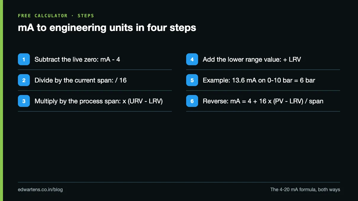
- Subtract the live zero: I - 4.
- Divide by the current span: (I - 4) / 16. This is the fraction of range, 0 to 1.
- Multiply by the process span: x (URV - LRV).
- Add the lower range value: + LRV.
Percent of span is step 2 multiplied by 100: % = (I - 4) / 16 x 100.
The reverse formula: value to mA
Going the other way is the same straight line read backwards:
- Subtract LRV from the value: PV - LRV.
- Divide by the span: (PV - LRV) / (URV - LRV).
- Multiply by 16 and add 4.
You need the reverse when you simulate a value with a loop calibrator, set an alarm on the transmitter itself, or work out what an analog output must send to a valve positioner for a given opening.
Worked example 1: pressure
A pressure transmitter is ranged 0 to 10 bar. The multimeter in series reads 13.6 mA.
- 13.6 - 4 = 9.6
- 9.6 / 16 = 0.6 (60% of span)
- 0.6 x 10 = 6
- 6 + 0 = 6 bar
Reverse: the process engineer wants a high alarm at 7.5 bar. 7.5 / 10 = 0.75; 0.75 x 16 = 12; 12 + 4 = 16 mA.
Worked example 2: level
A DP level transmitter on a vertical tank is ranged 0 to 4,000 mm. It reads 9.2 mA.
- 9.2 - 4 = 5.2
- 5.2 / 16 = 0.325
- 0.325 x 4,000 = 1,300 mm
If the tank is a vertical cylinder 2.5 m in diameter, the volume is pi x 1.25² x 1.3 = about 6.38 m³. The mA gives you height; the tank geometry gives you volume. For a horizontal cylinder the height-to-volume relation is not linear, which is why PLCs use a strapping table there.
Note that a DP transmitter measures pressure, not height. Liquid density is taken into account when the transmitter is ranged (the 20 mA point is set at the pressure that 4,000 mm of that liquid produces). If the liquid changes, the range must change too, or the level reading is wrong even though the formula is right. Our post on calibrating a pressure transmitter covers how the range points are checked.
Worked example 3: temperature with a negative range
A temperature transmitter is ranged -50 to 150 °C. It reads 12 mA.
- 12 - 4 = 8
- 8 / 16 = 0.5
- 0.5 x 200 (the span, 150 - (-50)) = 100
- 100 + (-50) = 50 °C
The common wrong answer is 75 °C, from taking half of 150. It forgets that the range starts at -50. Another check: 6.4 mA gives (2.4 / 16) x 200 - 50 = -20 °C, and 0 °C needs 4 + 16 x (50 / 200) = 8 mA.
One exception: square-root flow
An orifice plate or DP flow element produces a differential pressure proportional to the square of flow. If the transmitter outputs linear DP (no square-root extraction), then flow % = square root of DP %. At 12 mA, DP is 50% but flow is about 70.7%. Check whether square-root extraction is done in the transmitter or in the PLC, and make sure it is done exactly once. Doing it twice, or not at all, is a classic commissioning fault.
Lookup table: mA, percent and raw counts
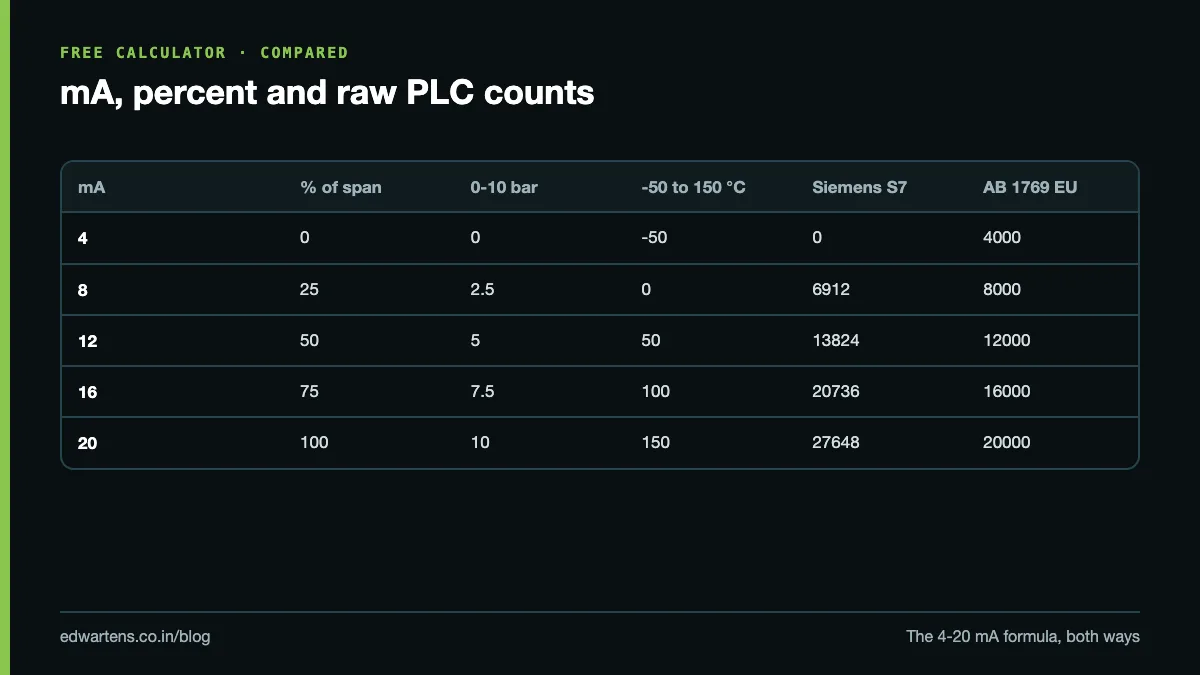
| mA | % of span | 0-10 bar | -50 to 150 °C | Siemens S7 count | AB 1769 eng. units |
|---|---|---|---|---|---|
| 4 | 0 | 0 | -50 | 0 | 4000 |
| 8 | 25 | 2.5 | 0 | 6912 | 8000 |
| 12 | 50 | 5 | 50 | 13824 | 12000 |
| 16 | 75 | 7.5 | 100 | 20736 | 16000 |
| 20 | 100 | 10 | 150 | 27648 | 20000 |
Raw PLC counts by brand
The PLC never sees milliamps. The analog card converts the current to an integer, and your program scales that integer. The general formula is the same straight line:
count = rawLo + (I - 4) / 16 x (rawHi - rawLo), and PV = LRV + (count - rawLo) / (rawHi - rawLo) x span.
| Platform | 4 mA | 20 mA | Notes |
|---|---|---|---|
| Siemens S7-1200, S7-1500, S7-300 | 0 | 27648 | Overrange up to 32511 (about 22.8 mA), undershoot down to -4864 (about 1.185 mA) |
| Allen-Bradley 1769 Compact I/O, Engineering Units format | 4000 | 20000 | One count per microamp, so the raw value reads like a meter |
| Allen-Bradley 1756 ControlLogix analog | set in config | set in config | The module can scale to floating-point engineering units you enter |
| Mitsubishi FX and Q series | mode-dependent | mode-dependent | The input mode sets the digital range; read the module manual |
| Generic 12-bit card | 0 | 4095 | Typical of low-cost modules |
| Generic 16-bit signed | 0 | 32767 | Offered as a preset in our calculator |
Why does Siemens use 27648 rather than 32767? It leaves room above and below the nominal range, so the card can still report a value for a signal slightly over 20 mA or under 4 mA before it declares overflow or underflow. In TIA Portal the usual way to scale is NORM_X then SCALE_X; our NORM_X and SCALE_X guide walks through it with the same numbers. Raw ranges also depend on how the channel is configured, so check the card's manual before trusting any table, including this one.
Worked count example: a Siemens card on the 0 to 10 bar transmitter reads 20736. 20736 / 27648 = 0.75, so the pressure is 7.5 bar and the loop current is 16 mA.
NAMUR NE43: when a reading is a fault
A 4-20 mA signal can carry a fault, but only if the transmitter and the PLC agree on where the fault zone starts. NAMUR recommendation NE43 is the convention most transmitters follow:
| Current | What it means |
|---|---|
| 3.8 to 20.5 mA | Measurement range. The value is valid, including slight under- and over-range of the process |
| 3.6 to 3.8 mA | Below range. The transmitter is saturated low, but has not declared a failure |
| 20.5 to 21.0 mA | Above range. Saturated high, not yet a failure |
| 3.6 mA or less | Failure signal, low (downscale alarm) |
| 21.0 mA or more | Failure signal, high (upscale alarm) |
| About 0 mA | No loop current: open wire, blown fuse or no 24 V supply |
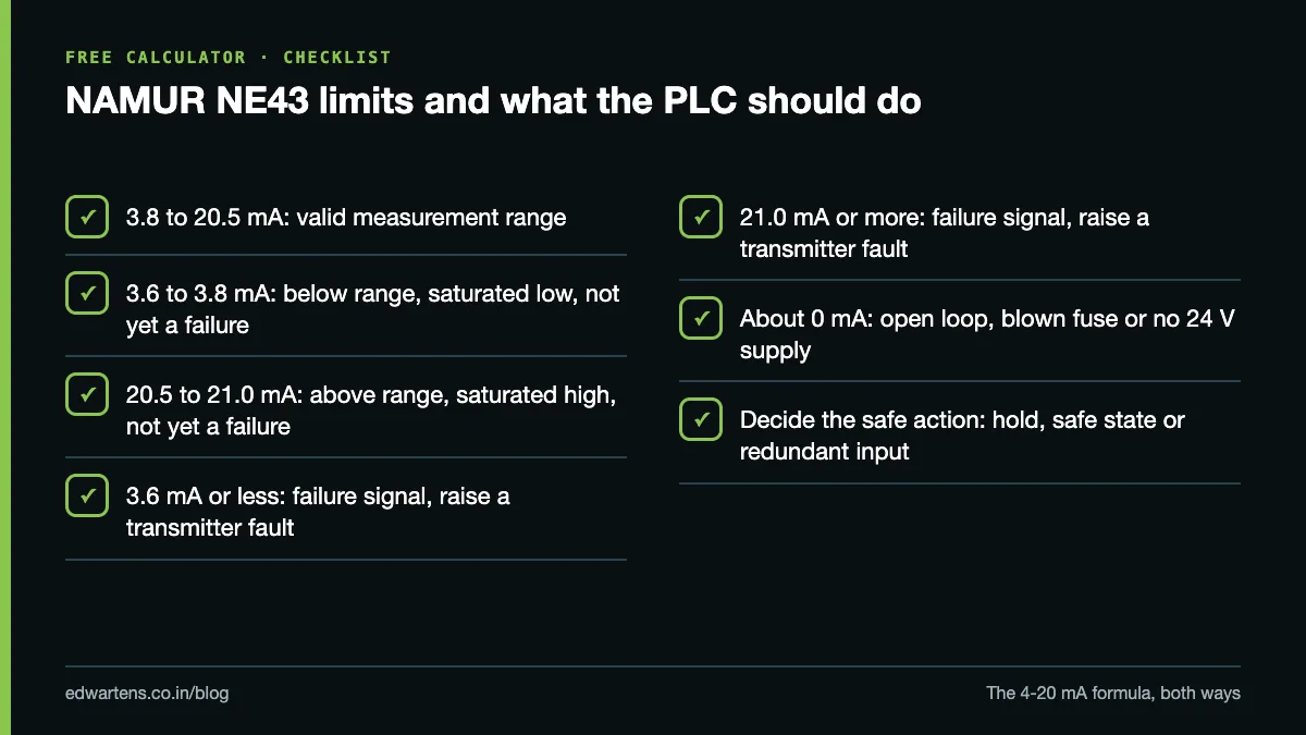
In the PLC, that means: clamp or flag values between 20 and 20.5 mA rather than showing 103% as if it were real, raise a "transmitter fault" alarm at or below 3.6 mA and at or above 21 mA, and decide what the logic does with a failed signal (hold last value, go to a safe state, or switch to a redundant transmitter). Whether a failed transmitter drives low or high is usually a jumper or setting on the transmitter, so check it matches what the logic expects. When the reading looks wrong and it is not obviously a fault, our 4-20 mA loop troubleshooting guide gives the measurement order.
Using the free calculator
The 4-20 mA Scaling Calculator needs no sign-up. You enter:
- Range low and range high, the values at 4 and 20 mA, and a unit (bar, °C, m³/h, anything).
- The direction: mA to value, value to mA, or percent to mA.
- The analog card's raw range: Siemens S7 (0-27648), 16-bit signed (0-32767), or Custom, where you type the counts at 4 and 20 mA (use 4000 and 20000 for an Allen-Bradley card in engineering-units format).
It returns the current, percent of span, the engineering value and the raw count, and warns you when the current is below 3.8 mA or above 20.5 mA.
Mistakes that cost an afternoon
- Forgetting the LRV. Any range that does not start at zero (-50 to 150 °C, 2 to 12 bar) breaks the "percent of URV" shortcut.
- Scaling twice. The transmitter is ranged 0-10 bar, the card is set to engineering units, and the PLC code scales again. The HMI then shows nonsense that is "nearly right".
- Square-root in two places, or in neither, on DP flow.
- Mixing up the card's range. Using 32767 in the code when the Siemens card reports 27648 makes every reading about 16% low.
- Ignoring the fault zone. A loop sitting at 3.5 mA is a fault, not "slightly below zero".
Learn it free
The free Instrumentation for PLC Engineers course covers converting between milliamps, percent and engineering units, scaling with NORM_X and SCALE_X, alarming on the scaled value, and holding a safe state when the signal cannot be trusted. If you are starting from zero, Industrial Instrumentation and Process Control covers pressure, level, flow and temperature measurement and the 4-20 mA calculation in both directions, including square-root flow. For the PLC side in depth, see Siemens TIA Portal PID Compact and Analog Processing. All three are free to learn with an account; the EDWartens Certificate of Completion is optional.
Frequently asked questions
Q: What is the formula to convert 4-20 mA to engineering units?
A: PV = LRV + (I - 4) / 16 x (URV - LRV), where LRV and URV are the values at 4 mA and 20 mA. For 12 mA on a 0 to 10 bar transmitter, that is 0 + 8 / 16 x 10 = 5 bar.
Q: What percentage is 12 mA in a 4-20 mA loop?
A: 50%. Each milliamp is 6.25% of span, so 8 mA is 25%, 12 mA is 50% and 16 mA is 75%.
Q: Why does Siemens use 27648 for 20 mA?
A: The S7 analog cards map the nominal range to 0 to 27648 and keep the counts above and below it for overrange and undershoot, up to 32511 and down to -4864 on a 4-20 mA channel. That lets the card report a slightly out-of-range signal before it declares a fault.
Q: What does 3.6 mA or 21 mA mean on a transmitter?
A: Under NAMUR NE43, 3.6 mA or less and 21 mA or more are failure signals from the transmitter. The valid measurement range is 3.8 to 20.5 mA.
Q: How do I convert mA back to a value with a negative range?
A: Use the same formula with the real LRV. On a -50 to 150 °C range, 12 mA is -50 + 0.5 x 200 = 50 °C.
Learn this, free
The courses that teach this
Every lesson, the written notes and the practice are free with an account. Only the certificate is optional and paid.