PLC Block Diagram and Architecture Explained

The short answer
A PLC block diagram has six blocks: a power supply, the CPU (processor plus memory), input modules, output modules, communication ports and a programming device. Field devices such as switches, sensors and transmitters feed the inputs, and actuators such as contactors, valves, lamps and drives hang off the outputs. Once per scan, a signal travels from the sensor through the input module into the input process image, the CPU executes the program, writes the output process image, and the output module switches the actuator. Physically, PLC architecture comes in three forms: compact (Siemens S7-1200, Allen-Bradley Micro850, Mitsubishi FX5U), modular (S7-1500, CompactLogix 5380) and rack or chassis based (ControlLogix, MELSEC iQ-R).
Watch: what a PLC is made of
The video above is What is a PLC. PLC Analog Module Digital Modules. Modular PLC. PLC Input Output modules. Animation by Instrumentation Academy, embedded with thanks. EDWartens is not affiliated with the creator. It runs about 9 minutes and is one of the lessons in our free Industrial Instrumentation and Process Control course. It animates a modular PLC and its digital and analog input and output modules, which makes the blocks easy to picture. The written guide below adds what the animation leaves out: memory types, output types, the scan sequence from a vendor manual, real compact, modular and rack examples, and an exam answer you can reproduce.
What is a PLC block diagram?
A PLC block diagram is a drawing that shows the functional parts of a programmable logic controller and the direction in which signals flow between them and the field devices. It is not a wiring diagram: it shows what each part does, not which terminal connects to which.
Siemens describes the S7-1200 CPU in exactly these terms. Its S7-1200 System Manual says the CPU "combines a microprocessor, an integrated power supply, input and output circuits" with built-in PROFINET in a compact housing. Every block in your diagram is in that sentence.
The blocks of a PLC, one by one
Power supply
The power supply converts the incoming supply (230 V AC or 24 V DC) into the low DC voltages the processor and module electronics need. On a compact PLC it is built in; on a modular or rack PLC it is a separate module. Siemens names its compact CPUs by supply, input and output type, so a CPU 1214C DC/DC/DC takes a 24 V DC supply, has DC inputs and has transistor (DC) outputs, while an AC/DC/Relay variant takes AC supply and has relay outputs.
CPU (processor)
The CPU reads the input states, executes the user program, updates timers, counters and data, writes the outputs, handles communication and runs self-diagnostics. If it detects an internal fault or the scan takes too long, it can stop or raise an error. Siemens' S7-1500 page calls the CPUs "the heart of the controller system" that execute the user program and network the controller with other automation components.
Memory: program, data and retentive
Exam books describe PLC memory in generic terms (ROM, RAM, EEPROM). Vendor manuals use their own names. This table maps one to the other using the S7-1200 System Manual.
Textbook term | What it holds | S7-1200 name | Survives power loss? |
|---|---|---|---|
ROM, firmware | The operating system that runs the scan | CPU firmware | Yes |
Program memory (EEPROM, flash) | User program, data and configuration as downloaded | Load memory, in the CPU or on a memory card | Yes |
Data memory (RAM) | Values used while running: process image, bit memory, timers, data blocks | Work memory | No, rebuilt from load memory at power-up |
Retentive memory | Selected values that must survive a power cut, such as counts and totals | Retentive memory | Yes |
The manual is explicit: load memory is non-volatile, work memory is "lost when power is removed" and restored by the CPU, and retentive memory stores selected values during power loss. In the 2012 edition's comparison table, every S7-1200 CPU from the 1211C to the 1215C has 10 Kbytes of retentive memory.
Input modules: digital and analog
An input module converts a field signal into a form the CPU can read and electrically isolates the field wiring from the processor, usually with an optocoupler, so a spike on a sensor cable does not reach the CPU.
- Digital inputs read on/off devices: push buttons, limit switches, proximity sensors, float switches. Common ratings are 24 V DC and 230 V AC.
- Analog inputs read continuous values: 4 to 20 mA or 0 to 10 V transmitters for pressure, level, flow and temperature. An analog-to-digital converter turns the signal into a number; on the S7-1200, 0 to 27648 represents the rated range of the input.
- Special inputs include RTD and thermocouple modules and high-speed counter inputs for encoders.
Output modules: relay, transistor and triac
An output module converts the CPU's output bits into a switched voltage or current that drives an actuator. The output type decides what you can drive.
Output type | Switches | Speed | Typical loads | Watch out for |
|---|---|---|---|---|
Relay | AC or DC | Slow, mechanical contacts | Contactor coils, solenoids, lamps at 24 V DC or 230 V AC | Contacts wear with every operation; S7-1200 built-in relay outputs cannot be used as pulse outputs |
Transistor (MOSFET) | DC only | Fast | 24 V DC solenoids, indicators, pulse trains for stepper and servo drives | Cannot switch AC; check sinking or sourcing type |
Triac | AC only | Fast, no moving parts | AC contactor coils, AC solenoids | Small off-state leakage current can hold in very light loads |
Analog | 4 to 20 mA or 0 to 10 V | Continuous | Control valves, VFD speed reference | Scaling and wiring polarity |
The S7-1200 manual says that on CPU models with relay outputs you must add a digital signal board to use the pulse outputs, which is a neat real-world example of why output type matters.
Communication ports
Communication ports connect the PLC to the programming PC, HMIs, drives, remote I/O and other PLCs. The S7-1200 has a PROFINET port on the CPU and takes up to three communication modules on its left side for PROFIBUS, RS232, RS485 or AS-i. The Allen-Bradley Micro850 has a USB programming port, a non-isolated serial port for RS-232 and RS-485, and an Ethernet port.
Programming device
A PC with the vendor's engineering software is the programming device: TIA Portal for Siemens S7-1200 and S7-1500, Connected Components Workbench for Micro800, Studio 5000 Logix Designer for CompactLogix and ControlLogix, GX Works3 for MELSEC iQ-F and iQ-R, and ISPSoft or DIADesigner for Delta. Older textbooks show a handheld programmer; you will rarely meet one on a modern site. Most of these tools support the IEC 61131-3 languages.
Field devices
Field devices are not part of the PLC but always appear in the block diagram: sensors and switches on the input side, actuators on the output side. Drawing them makes the signal direction obvious, which is what examiners look for.
How a signal flows from sensor to actuator
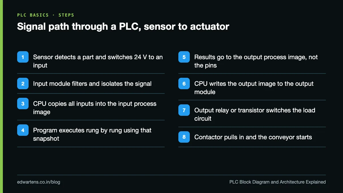
The S7-1200 System Manual describes the process image as "a snapshot of the physical inputs and outputs". Using a proximity sensor that starts a conveyor:
- The sensor detects a part and switches 24 V to an input terminal.
- The input module filters the signal, isolates it and presents it to the CPU.
- Just before the program runs, the CPU copies all physical inputs into the input process image, so values stay consistent for the whole scan.
- The program executes rung by rung, reading from the process image.
- Results are written to the output process image, not straight to the terminals. Siemens notes this prevents outputs flickering when a bit changes state several times in one scan.
- The CPU writes the output process image to the physical outputs.
- The output module switches the contactor coil, and the conveyor starts.
Siemens lists the loop as write outputs, read inputs, execute program; it is the same circle entered at a different point. Rockwell Logix controllers work differently: each I/O module is updated at its own requested packet interval (RPI), asynchronously to the execution of the logic, as Rockwell's Logix 5000 Controllers I/O and Tag Data programming manual explains. Our PLC scan cycle guide shows why rung order matters as a result.
Compact vs modular vs rack-mounted PLC: the types of PLC
When people search "types of PLC", they usually mean the physical architecture. There are three.
Compact (fixed or brick) PLC. Power supply, CPU and I/O share one housing, with expansion modules clipped to the side. The S7-1200 CPU 1214C has 14 digital inputs and 10 digital outputs on board, takes up to 8 signal modules on the right, up to 3 communication modules on the left and one signal board on the front. Rockwell's Micro850 comes in 24-point and 48-point versions and reaches up to 192 I/O points with up to five plug-in modules and four expansion I/O modules. Mitsubishi describes the MELSEC iQ-F FX5U CPU module as an "all-in-one" power supply, CPU and I/O unit. Siemens LOGO! and Delta DVP are also compact.
Modular PLC. The CPU, power supply and each I/O function are separate modules mounted side by side on a rail. Siemens' S7-1500 is built from "CPUs, power supplies, signal modules, technology modules and communication modules", is rated IP20 and is meant for installation in a control cabinet. Rockwell's CompactLogix 5380 supports up to 31 local Compact 5000 I/O modules, memory options from 0.6 to 10 MB and integrated motion for up to 32 axes.
Rack-mounted (chassis) PLC. Modules slide into a chassis or base unit whose backplane carries power and data. ControlLogix chassis have up to 17 slots and support removal and insertion under power and full controller redundancy. MELSEC iQ-R uses a base unit that holds the power supply module, CPU and other modules, and supports multi-CPU systems.
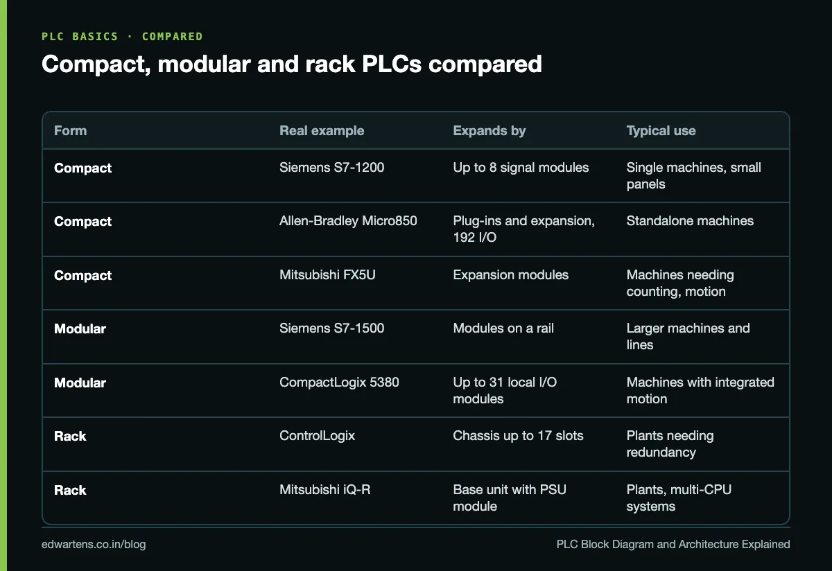
Compact controllers dominate single machines; modular and rack systems appear where I/O counts, motion, redundancy or hot-swapping justify them. If you want to see the compact end in practice, our free Allen-Bradley Micro800 with Connected Components Workbench and Siemens Small Controllers: LOGO! 8 and S7-200 SMART courses both start from the hardware.
Types of PLC modules
The iQ-R product list is a good map of what a large system can contain:
- Power supply module: powers the CPU and modules on the base or rail.
- CPU module: runs the program; some systems allow several CPUs.
- Digital I/O modules: bit signals in and out.
- Analog modules: voltage and current in and out.
- Temperature modules: RTD and thermocouple inputs, sometimes with built-in control.
- High-speed counter and positioning or motion modules: encoders, pulse trains, servo axes.
- Communication or network modules: fieldbuses, Ethernet protocols, serial links.
- Safety modules and CPUs: for safety functions, kept separate from standard logic.
How these are addressed in the program differs by brand; our guide to PLC data types and addressing across brands covers I0.0, %I, X0 and tag-based styles side by side.
Sinking and sourcing in one paragraph
A sourcing device supplies current to the circuit (it switches +24 V); a sinking device provides the path to 0 V. A sourcing (PNP) sensor needs a sinking input, and a sinking (NPN) sensor needs a sourcing input. The S7-1200 manual shows its DC inputs wired both ways and lists the transistor outputs on its DC/DC/DC CPUs as "Solid state - MOSFET (sourcing)", so a load on those outputs connects between the output and 0 V. Get this wrong and the input never turns on. Our PNP vs NPN sensor wiring guide has the wiring drawings.
How to write the PLC block diagram answer in an exam
For a 10-mark "Draw the block diagram of a PLC and explain each block" question, this structure covers what examiners look for.
- Draw the CPU in the centre as a large box split into "Processor" and "Memory (program, data, retentive)".
- Draw the input module on the left and the output module on the right, each joined to the CPU with an arrow pointing in the direction of the signal.
- Draw field inputs (push button, limit switch, sensor, transmitter) to the left of the input module, and field outputs (contactor, solenoid valve, lamp, motor drive) to the right of the output module.
- Draw the power supply below the CPU with lines to the CPU and both I/O modules.
- Draw the programming device and communication port above the CPU with a two-way arrow.
- Explain each block in two or three lines, using the definitions in this guide.
- Add the scan cycle in four lines: read inputs, execute program, update outputs, housekeeping and communication.
- Finish with types and one example: compact (S7-1200), modular (S7-1500), rack (ControlLogix), and why a plant chooses each.
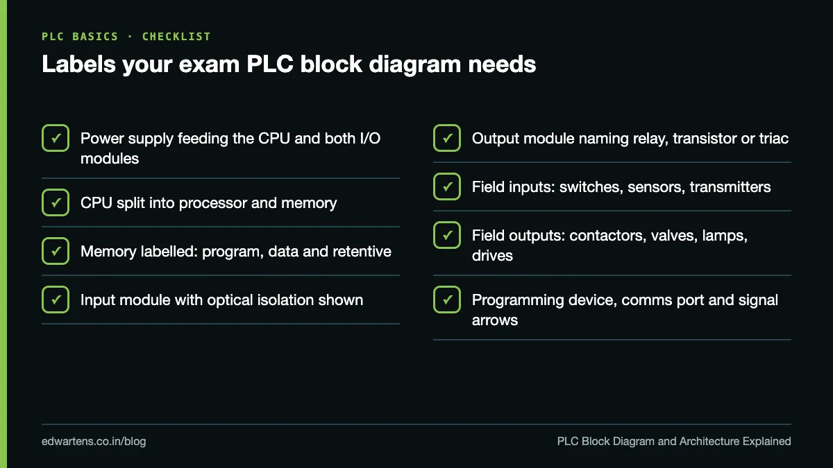
Two extras lift an answer: mention optical isolation in the input module, and name the three output types with one load each. If a question asks how a PLC differs from a microcontroller board, our PLC vs microcontroller guide gives the practical differences, and what PLC programming is and why to learn it puts the hardware in context.
From diagram to real hardware
Block diagrams make sense quickly once you have configured a real CPU and added modules to it. The free Siemens TIA Portal in Three Hours course starts with hardware configuration, and CODESYS and IEC 61131-3 Programming shows the same blocks from a vendor-neutral angle. If you prefer to configure and wire PLC training panels with an instructor, see our classroom PLC training in Bangalore at Electronic City.
Frequently asked questions
Q: What are the main parts of a PLC?
A: Power supply, CPU (processor and memory), input modules, output modules, communication ports and a programming device. Field devices connect to the input and output modules but are not part of the PLC itself.
Q: What is the difference between PLC architecture and a PLC block diagram?
A: The block diagram shows the functional parts and signal flow. Architecture also covers how those parts are physically built and expanded: compact, modular or rack-mounted.
Q: What are the types of PLC used in industry?
A: By construction: compact (S7-1200, Micro850, FX5U), modular (S7-1500, CompactLogix) and rack or chassis based (ControlLogix, MELSEC iQ-R). PLCs are also described by output type: relay, transistor or triac.
Q: Which memory stores the PLC program?
A: Non-volatile program memory, called load memory on Siemens CPUs, which can sit inside the CPU or on a memory card. Parts of it are copied into volatile work memory to run.
Q: Why does a PLC input module use optical isolation?
A: It separates the field wiring from the CPU electronics, so voltage spikes and noise on sensor cables do not damage or disturb the processor.
Q: What are the types of PLC output modules?
A: Relay (AC or DC loads, slow, contacts wear), transistor (DC only, fast, suitable for pulses) and triac (AC only, solid state). Analog output modules give 4 to 20 mA or 0 to 10 V for valves and drives.
Q: Can I get the PLC block diagram with explanation as a PDF?
A: Use your browser's print option and choose Save as PDF to keep this page for revision. For vendor detail, the S7-1200 System Manual linked above is a free PDF from Siemens.
Learn this, free
The courses that teach this
Every lesson, the written notes and the practice are free with an account. Only the certificate is optional and paid.


