PNP vs NPN Sensor Wiring to a PLC, Explained on Video

The short answer
A PNP sensor switches +24 V onto its signal wire, so it needs a sinking input: current flows into the input terminal and returns through the common to 0 V. An NPN sensor switches 0 V onto its signal wire, so it needs a sourcing input: the common goes to +24 V and current flows out of the input into the sensor. On a Siemens S7-1200 you choose by wiring the 1M terminal to 0 V (PNP) or +24 V (NPN); on Mitsubishi FX3/FX5 and Delta DVP you make the same choice with the S/S terminal.
Watch the lesson
The video above is Sinking and Sourcing PLC Inputs with PNP NPN Sensors by Tim Wilborne, embedded with thanks. EDWartens is not affiliated with the creator. It runs about 17 minutes and is one of the lessons in our free Control Panel Design and Building course.
First, the lesson explains what "sinking" and "sourcing" mean at a PLC input in terms of which way current flows. Next it wires a PNP sensor to an input card with the common taken to 0 V, then an NPN sensor with the common taken to +24 V. It then shows how to prove a sensor's output with a multimeter before blaming the PLC, and why one input group cannot serve both sensor types unless the commons are split. The written walkthrough below covers the same ground with Indian panel brands, so you can use it at the bench without replaying the video.
The three wires
Almost every 3-wire DC proximity or photoelectric sensor sold in India follows the IEC colour code:
| Wire | Colour | Connect to |
|---|---|---|
| Supply positive | Brown | +24 V DC |
| Supply negative | Blue | 0 V DC |
| Output (normally open) | Black | PLC input terminal |
| Second output (4-wire types) | White | Second input, often the NC or complementary output |
The brown and blue wires only power the sensor's electronics. The black wire is the switch. The question of PNP or NPN is simply: when the sensor detects a target, does it connect the black wire to brown (+24 V) or to blue (0 V)?
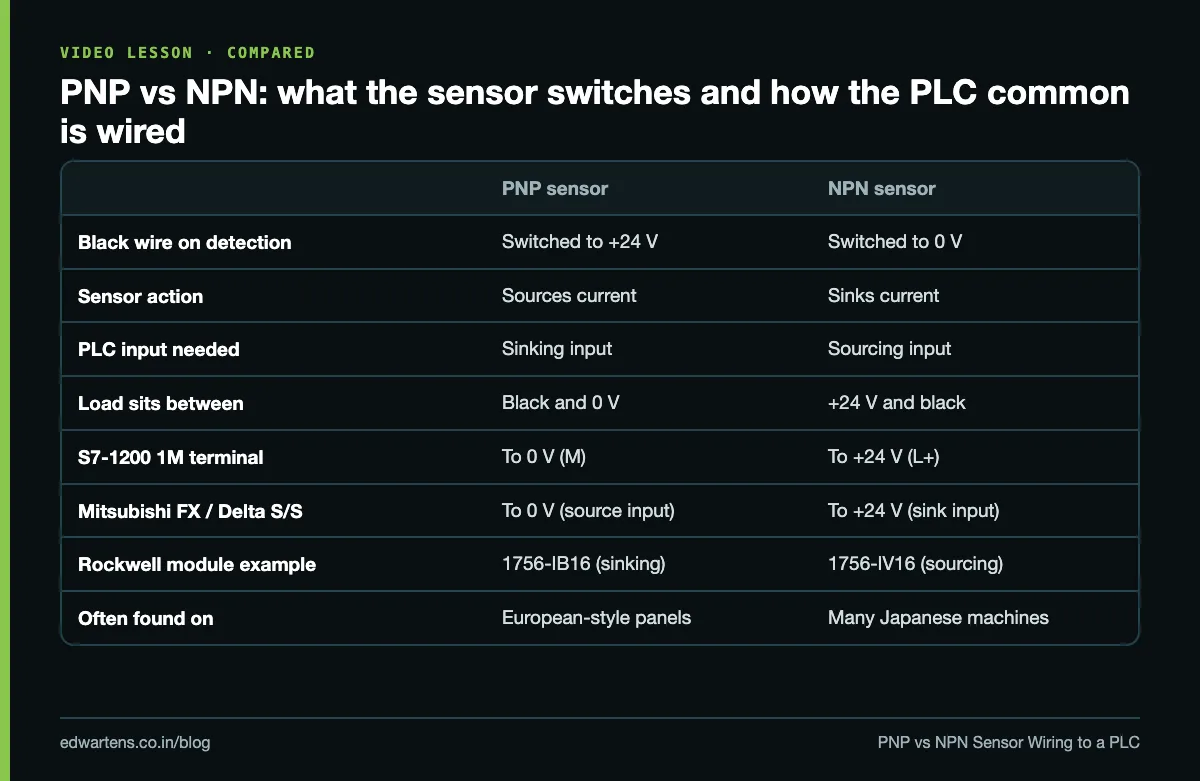
- PNP (sourcing sensor): on detection, black is connected to +24 V. The load (the PLC input) sits between black and 0 V.
- NPN (sinking sensor): on detection, black is connected to 0 V. The load sits between +24 V and black.
Sinking and sourcing inputs, without the confusion
The words describe the PLC input, and the input is always the opposite of the sensor. A PNP sensor sources current, so the input must sink it. An NPN sensor sinks current, so the input must source it. If you remember only one rule, remember this: the common decides. If the input group's common goes to 0 V, the group takes PNP sensors. If the common goes to +24 V, the group takes NPN sensors.
One warning before the brand-by-brand section: Japanese and Taiwanese manuals often name the wiring after the sensor, not after the input. Mitsubishi and Delta call NPN wiring "sink input" and PNP wiring "source input". Siemens and Rockwell call the PNP arrangement a sinking input. The same physical wiring gets opposite names, so always go by where the common terminal is connected, never by the word.
Wiring by brand
Siemens S7-1200 (1M terminal)
The onboard DC inputs of a CPU 1214C DC/DC/DC are rated sink/source and share one common, labelled 1M.
- For PNP sensors: connect 1M to M (0 V) of the 24 V supply. Brown to L+, blue to M, black to I0.0.
- For NPN sensors: connect 1M to L+ (+24 V). Brown to L+, blue to M, black to I0.0.
- The CPU's own 24 V DC sensor supply output (its own L+ and M terminals) can feed a few sensors, but its current is limited. Check the figure in the CPU datasheet and use a separate 24 V SMPS for anything more than a handful.
Because all fourteen onboard inputs of a 1214C share 1M, you cannot put a PNP and an NPN sensor on the onboard inputs at the same time. If you must mix them, use a signal module whose inputs are split into separately wired common groups (check the module datasheet), or bring the odd sensor in through an interposing relay.
Mitsubishi FX3G, FX3U and FX5U (S/S terminal)
These have an S/S terminal that sets the whole input block:
- NPN sensors ("sink input" in Mitsubishi's words): S/S to +24 V.
- PNP sensors ("source input"): S/S to 0 V.
On AC-powered FX3 units with a built-in 24 V service supply, the terminals are labelled 24V and 0V on the input side; on DC-powered units, the S/S link goes to the + or minus of your external supply. Many older FX units without an S/S terminal were fixed for NPN sensors, which is one reason many older Japanese machines in Indian plants still use NPN throughout.
Delta DVP (S/S terminal)
Delta follows the same naming as Mitsubishi. On DVP-SS2, ES2 and similar series:
- NPN sensors ("sink mode"): S/S to +24 V.
- PNP sensors ("source mode"): S/S to 0 V.
Allen-Bradley
Rockwell modules are named by the input. A sinking DC module such as the 1756-IB16 takes PNP sensors; a sourcing module such as the 1756-IV16 takes NPN. Many CompactLogix and Micro800 inputs are sink/source, so the common wiring decides, exactly as on Siemens.
Which one will you meet in India?
Panels built to European practice, and most new machines built in India around Siemens, Schneider or Rockwell, use PNP. Many machines from Japan, Taiwan and older Asian OEMs use NPN. Both work equally well; the only real requirement is that every sensor on one common matches that common. When you buy a replacement, match the type on the old sensor's label, not what is cheaper on the shelf.
Identify an unknown sensor with a multimeter
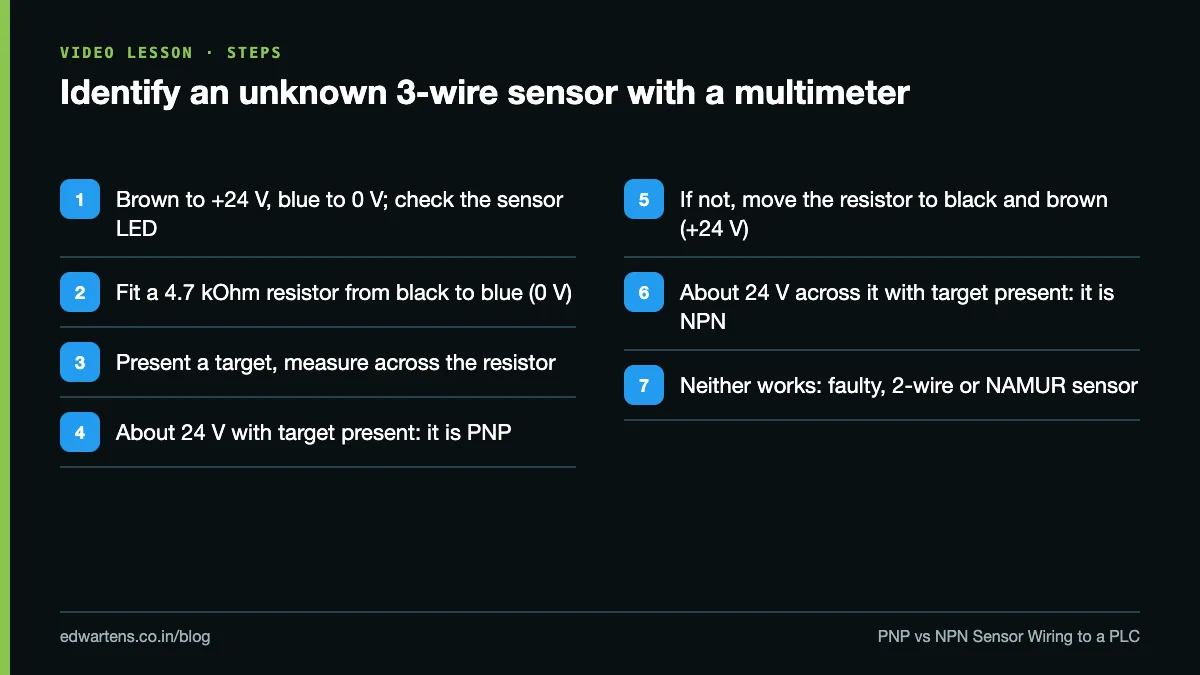
The label is worn off and nobody knows if the sensor is PNP or NPN. Do not guess by plugging it into the PLC. Test it on the bench with a 24 V supply, a resistor of about 4.7 kOhm (a quarter watt is enough: 24 x 24 / 4700 is about 0.12 W) and a multimeter.
- Power the sensor: brown to +24 V, blue to 0 V. Its LED should light when you present a target.
- Connect the resistor from black to blue (0 V). Measure across the resistor. If it reads about 24 V when the target is present and near 0 V when it is not, the sensor is PNP.
- If not, move the resistor to between black and brown (+24 V) and measure across it. If it reads about 24 V with the target present, the sensor is NPN.
- If neither step gives a clean change, the sensor is faulty, or it is a 2-wire or a NAMUR type that needs a different test.
The resistor matters. Without a load, an open-collector output floats when it is off and a digital meter can show a misleading voltage. The resistor gives the meter something real to measure.
Common mistakes
- PNP and NPN on one common. One of them will never switch the input, or the input will stay on. Split the commons or use an interposing relay.
- The common not wired at all. The sensor LED lights, the PLC input LED does not. On an S7-1200 the 1M wire is the first thing to check.
- Measuring to the wrong rail. A PNP output is measured against 0 V; an NPN output against +24 V. Measure an NPN output against 0 V and you see the inverse of what you expect.
- Two-wire sensors on a sensitive input. A 2-wire sensor leaks a small current when off. If that leakage is more than the input's maximum off-state current, the input never turns off. Compare both datasheet figures before you fit one.
- Sensor supply from a different 0 V. If the sensor's blue wire goes to a different 24 V supply from the one feeding the common, the circuit has no return path. Tie the 0 V of both supplies together if the design allows, or feed the sensors from the same supply.
- Mixing up the names. "Sink input" on a Mitsubishi drawing is NPN wiring. Read the terminal, not the word.
Practice task
On paper or on a trainer, wire one PNP and one NPN proximity sensor to a PLC that has two separately wired input groups. Mark the 24 V supply, the common of each group, each sensor's three colours and the input address. Then write the expected voltage at the black wire, measured to 0 V, with and without a target for each sensor. Done means your table shows the PNP output at about 24 V with a target and the NPN output at about 0 V with a target.
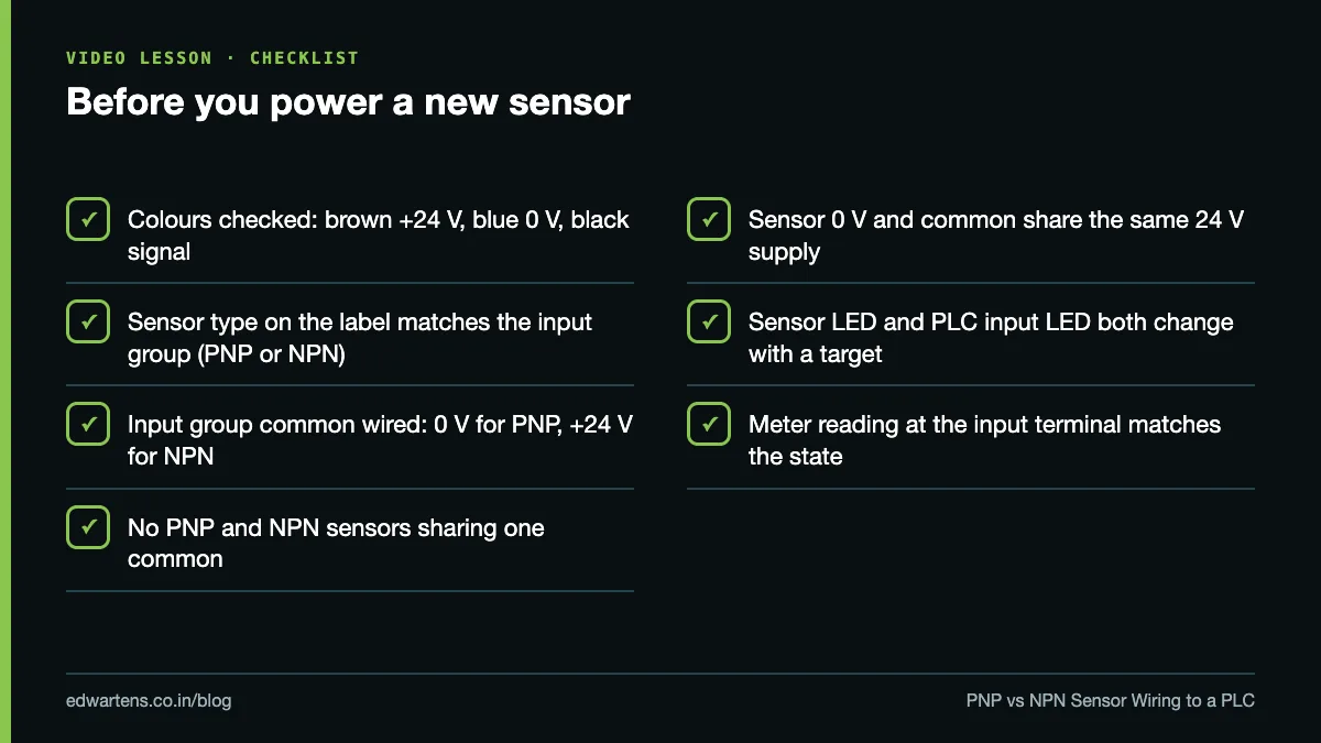
Before you power anything on site, run through the checklist below, and follow our I/O loop checking procedure to prove each input end to end.
Learn it free
Sensors, commons and noise are a full module in the free Control Panel Design and Building course, with written notes and a practice task. If you want to write the logic behind those inputs, start the free Siemens TIA Portal course; Mitsubishi and Delta users can take Mitsubishi FX with GX Works2 or Delta DVP with ISPSoft. Learning is free with an account; an optional EDWartens Certificate of Completion is available if you pass the final assessment. For the panel wiring rules around all of this, read control panel wiring standards in India.
Frequently asked questions
Q: Which is better, PNP or NPN?
A: Neither is better electrically. PNP is more common on European-style panels and new Indian machines, and NPN on many Japanese machines, so match whatever the rest of the machine uses.
Q: Can I connect a PNP sensor to an NPN input?
A: Not directly. Either rewire the input group's common so it becomes a sinking input, or use an interposing relay or a PNP-to-NPN converter module.
Q: What does the 1M terminal do on an S7-1200?
A: It is the common return for the onboard inputs. Connect it to 0 V for PNP sensors or to +24 V for NPN sensors.
Q: Why does Mitsubishi call NPN wiring "sink input"?
A: Mitsubishi names the wiring after the external device, which sinks current. Siemens and Rockwell name it after the input, which then sources current, so check where S/S or the common is connected rather than relying on the word.
Q: How do I know if a sensor is PNP or NPN without a label?
A: Power it from 24 V, put a 4.7 kOhm resistor from the black wire to 0 V and measure across it with a target present. About 24 V means PNP; if not, move the resistor to between black and +24 V, and 24 V there means NPN.
Learn this, free
The courses that teach this
Every lesson, the written notes and the practice are free with an account. Only the certificate is optional and paid.