XIC, XIO and OTE in Studio 5000: A Video Walkthrough

The short answer
In Studio 5000, XIC (Examine If Closed) is true when its bit is 1, XIO (Examine If Open) is true when its bit is 0, and OTE (Output Energize) writes the rung's result to its bit on every scan: 1 if the rung is true, 0 if it is false. None of the three describes the field device. An XIC on a normally closed stop button is correct, because that button's input bit is 1 when it is healthy.
Watch the lesson
The video above is Studio 5000 XIC XIO and OTE Bit Instructions Controllogix Compactlogix by Tim Wilborne, embedded with thanks. EDWartens is not affiliated with the creator. It runs about 10 minutes and is used in the "Bit Instructions: XIC, XIO and OTE" module of our free Allen-Bradley Studio 5000 course.
First, the lesson introduces XIC and shows that it goes true when its bit is 1. Next it does the same for XIO, which goes true when its bit is 0. Then it adds OTE and shows the rung result being written to a bit. Along the way it creates tags, toggles bits online and watches the rung highlighting change, then combines the three instructions into a simple motor rung. The written version below adds a truth table, the stop-button trap and a practice task you can check yourself against.
The one idea that clears up everything
Beginners hear "XIC is a normally open contact and XIO is a normally closed contact" and then wire a normally closed stop button to an XIO. The motor will not start. The fix is to stop thinking about contacts and think about bits:
- XIC asks: is this bit 1? If yes, the instruction is true and passes rung continuity.
- XIO asks: is this bit 0? If yes, the instruction is true and passes rung continuity.
- OTE says: whatever the rung is when the scan reaches me, write it to this bit.
The field device decides the bit. A normally open start button gives a 1 when pressed. A normally closed stop button gives a 1 when not pressed and a 0 when pressed or when its wire breaks.
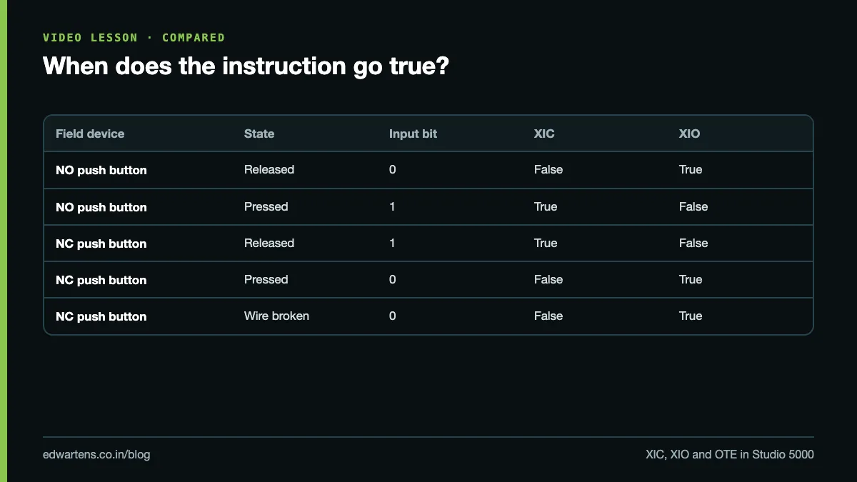
Truth table
| Field device | Button state | Input bit | XIC result | XIO result |
|---|---|---|---|---|
| NO push button | Released | 0 | False | True |
| NO push button | Pressed | 1 | True | False |
| NC push button | Released | 1 | True | False |
| NC push button | Pressed | 0 | False | True |
| NC push button | Wire broken | 0 | False | True |
Read the last three rows carefully. With an NC stop button, an XIC passes power while the button is healthy and released, and blocks it when the button is pressed or the wire is cut. That is why stop circuits use NC buttons with XIC in logic: a broken wire stops the machine instead of making the stop button useless.
Step by step in Studio 5000
1. Create the tags
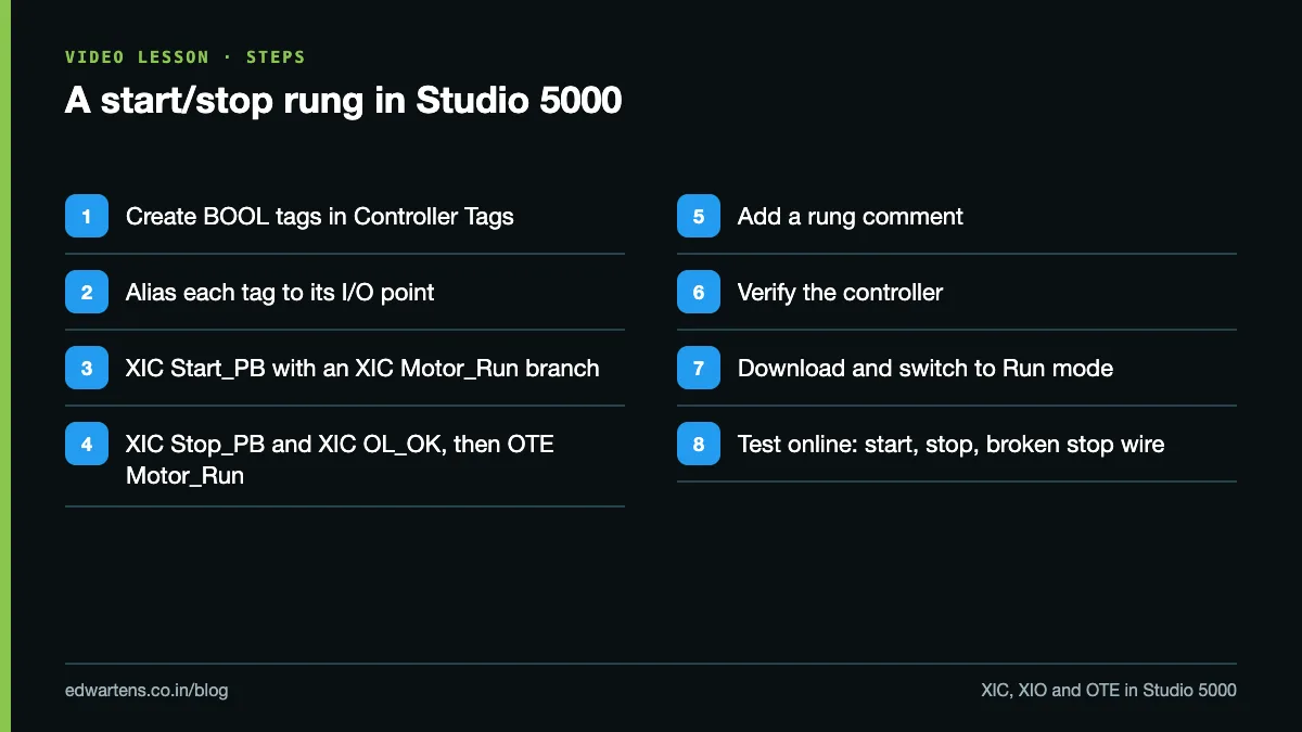
In the Controller Organizer, open Controller Tags and add BOOL tags:
| Tag | Type | Alias for (example) | Meaning |
|---|---|---|---|
| Start_PB | BOOL | Local:1:I.Data.0 | Green start, NO |
| Stop_PB | BOOL | Local:1:I.Data.1 | Red stop, wired NC |
| OL_OK | BOOL | Local:1:I.Data.2 | Overload NC contact 95-96 |
| Motor_Run | BOOL | Local:2:O.Data.0 | Contactor coil |
The exact I/O path depends on your controller and module; the example above is the style used for 1769 Compact I/O in slots 1 and 2. Use Alias tags so the logic reads Start_PB rather than a raw module address. If the hardware changes, you change the alias, not every rung.
2. Write the rung
Open MainProgram, MainRoutine. Build the rung:
- An XIC on Start_PB.
- A branch around it with an XIC on Motor_Run (the seal-in, or holding contact).
- After the branch, an XIC on Stop_PB, then an XIC on OL_OK.
- An OTE on Motor_Run at the right.
In Rockwell's neutral text, which you can type straight into a rung, it reads:
[XIC(Start_PB) ,XIC(Motor_Run) ]XIC(Stop_PB)XIC(OL_OK)OTE(Motor_Run);
Press start: Start_PB is 1, the branch passes, Stop_PB and OL_OK are 1, so OTE writes 1 to Motor_Run. Release start: the XIC on Motor_Run now holds the rung true. Press stop: Stop_PB drops to 0, its XIC goes false, OTE writes 0, and the seal-in releases. The whole pattern, and why stop always wins, is explained in our post on the seal-in circuit.
3. Add a rung comment
Right-click the rung and add a comment such as "Conveyor motor start/stop with seal-in. Stop and overload are NC, so XIC passes when healthy." That one sentence saves the next engineer ten minutes.
4. Verify, download, test
Use Logic, Verify, Controller to check for errors. Then Communications, Who Active, select your controller, Download, and switch to Run mode. Go online and watch the highlighting: an instruction drawn in green is true. Toggle the inputs (or, on a test bench, use the force or toggle-bit options with care) and check each row of the truth table.
How OTE really behaves
OTE is non-retentive. On every scan where the processor reaches it, it writes the rung result. If the rung is false, it writes 0. Two consequences catch people out:
- Double OTE on one bit. Two rungs both with OTE(Motor_Run): the second one, lower in the routine, overwrites the first on every scan. The first rung appears to do nothing. Use one OTE per bit and combine the conditions in branches.
- Prescan. When the controller goes into Run, it prescans the logic and OTE bits are cleared. A motor running before a mode change will not restart by itself, which is what you want.
If you need a bit that stays set after the rung goes false, that is OTL (latch) and OTU (unlatch), which are retentive and need deliberate handling on power-up.
Common mistakes
- XIO on an NC stop button. A double negative: the motor runs only while stop is pressed. Use XIC.
- Two OTEs on the same tag. The last one in scan order wins. Search the tag's cross-reference before adding an OTE.
- No aliases. Rungs full of Local:1:I.Data.0 are hard to read and hard to change.
- No rung comments. Studio 5000 makes comments easy; use them.
- Edits made offline, never downloaded. The project on your laptop and the logic in the controller drift apart. Go online and compare before you leave site.
- Overload contact left out of the logic. The hardwired overload should still break the coil circuit, but feeding its status into the PLC lets you alarm it.
Practice task
Build the start/stop rung above with aliased tags and a rung comment. Then prove three things online or in a simulator: start seals in, stop drops the motor even while start is held, and setting Stop_PB to 0 (simulating a broken wire) also drops the motor. If you have no Studio 5000 licence, the free Connected Components Workbench with its Micro800 simulator lets you build the same logic with IEC contacts and coils; our free Micro800 with CCW course covers it.
Learn it free
The free Allen-Bradley Studio 5000 course takes you from these bit instructions into timers, counters and program structure, with written notes and a 15-question final assessment. Next, read TON, TOF and TONR timers and try the worked problems in PLC ladder logic examples with solutions. If you also work on Siemens, the TIA Portal vs Studio 5000 comparison maps one to the other.
Frequently asked questions
Q: Is XIO the same as a normally closed contact?
A: Only in symbol. XIO is true when its bit is 0; it says nothing about how the field device is wired, so an NC field button usually needs an XIC.
Q: What does XIC stand for in Allen-Bradley?
A: Examine If Closed. It is true when the bit it examines is 1.
Q: What happens if I use OTE twice on the same tag?
A: The OTE lower in the scan writes last and wins every scan, so the earlier rung appears to have no effect. Use one OTE per tag.
Q: What is the difference between OTE and OTL?
A: OTE writes the rung result every scan and goes to 0 when the rung is false. OTL sets the bit and leaves it set until an OTU clears it.
Q: Can I practise XIC and XIO without a Studio 5000 licence?
A: Yes. Connected Components Workbench is free and includes a Micro800 simulator, which uses IEC contacts and coils that behave the same way.
Learn this, free
The courses that teach this
Every lesson, the written notes and the practice are free with an account. Only the certificate is optional and paid.