3-Wire Start-Stop Motor Starter Wiring, Step by Step

The short answer
A 3-wire start/stop circuit puts a normally closed stop button, a normally open start button and the contactor coil (A1-A2) in series, with the contactor's own normally open auxiliary contact (13-14) wired in parallel with the start button. Pressing start energises the coil, the 13-14 contact closes and holds it in after you let go, and pressing stop or tripping the overload (95-96) breaks the circuit. After a power failure the contactor drops out and stays out until someone presses start again.
Watch the lesson
The video above is Wiring a Three Wire Magnetic Motor Starter by Jim Pytel, embedded with thanks. EDWartens is not affiliated with the creator. It runs about 16 minutes and is used in the magnetic starters module of our free Industrial Motor Control course.
First, the lesson reads the three-wire schematic before any wire is touched. Next it wires the control circuit: stop, start and the auxiliary contact that seals the coil in. Then it brings the overload contact into the coil circuit and wires the power side to the motor, before powering up and testing start, stop and power-loss behaviour. The video uses North American hardware and terminology; the walkthrough below uses IEC terminal numbers and the components you will find in an Indian panel.
Why it is called 3-wire
Count the wires between the panel and a remote push-button station: one to the stop button, one between stop and start, and one back from start to the coil. The third wire carries the holding contact's connection. The important difference is not the wire count but the behaviour:
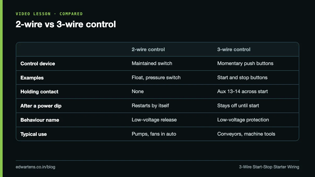
| 2-wire control | 3-wire control | |
|---|---|---|
| Control device | Maintained: float switch, pressure switch, thermostat, selector | Momentary start and stop push buttons |
| Holding contact | None | Contactor aux 13-14 across start |
| After a power dip | Restarts by itself when power returns | Stays off until start is pressed |
| Name of the behaviour | Low-voltage release | Low-voltage protection |
| Typical use | Pumps, fans, compressors in auto | Conveyors, machine tools, anything an operator stands near |
A machine that restarts by itself after a power cut can injure someone, which is why operator-attended machines use 3-wire control.
The parts and their terminals
| Part | Terminals | Notes |
|---|---|---|
| Motor protection breaker (MPCB) or MCB/fuses | 1-3-5 in, 2-4-6 out | Short-circuit protection for the motor feeder |
| Contactor main contacts | 1/L1, 3/L2, 5/L3 to 2/T1, 4/T2, 6/T3 | Switches the motor |
| Contactor coil | A1, A2 | Coil voltage must match the control supply |
| Contactor auxiliary NO | 13-14 | The holding (seal-in) contact |
| Thermal overload relay | Main 2-4-6 out; NC 95-96, NO 97-98 | 95-96 opens on overload |
| Stop push button | NC block | Red is the usual Indian practice |
| Start push button | NO block | Green is the usual Indian practice |
| Control fuse or MCB | Protects the control wiring |
Control voltage in Indian panels is most often 230 V AC (phase and neutral), 110 V AC from a control transformer, or 24 V DC. Whatever you choose, the coil must be rated for it. A 230 V coil on 24 V DC will not pull in; a 24 V coil on 230 V will burn out.
For sizing the contactor, overload and breaker to the motor, see how to select a contactor, overload relay and breaker and the motor full load current chart at 415 V. For whether this starter is right for the motor at all, read DOL vs star-delta vs soft starter vs VFD.
The control circuit, wire by wire
With a 230 V AC control supply taken from L1 and neutral through a control MCB, number the wires as you go:
- Wire 1: control MCB output to overload contact 95.
- Wire 2: overload 96 to the stop button (NC), first terminal.
- Wire 3: stop button second terminal to the start button (NO) first terminal, and to contactor aux 13.
- Wire 4: start button second terminal to coil A1, and to contactor aux 14.
- Wire 5 (N): coil A2 to neutral.
Check the shape: stop and overload are in series with everything; start and 13-14 are in parallel with each other; the coil is last. Some panel builders put the overload contact after the coil, between A2 and neutral; that is also valid, as long as it is in series with the coil.
For a remote station, the stop buttons of every station go in series and the start buttons go in parallel. Any stop drops the motor; any start runs it.
The power circuit
- Three-phase supply into the MPCB (or MCB/fuses) at 1-3-5.
- MPCB 2-4-6 to contactor 1/L1, 3/L2, 5/L3.
- Contactor 2/T1, 4/T2, 6/T3 into the overload relay (it usually plugs directly under the contactor).
- Overload output to the motor terminal box U1, V1, W1, with the motor linked in star or delta as its nameplate requires for 415 V.
- Earth the motor body and the panel.
Set the overload to the motor's nameplate full-load current.
Wiring order and the dead test
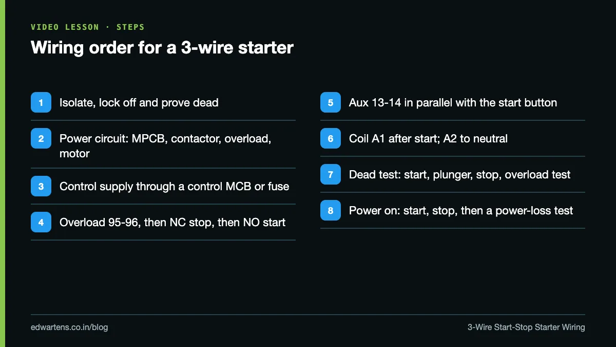
Before you switch on, test the control circuit dead with a multimeter on resistance, across the control circuit's supply points (the control MCB output and the neutral link, with the control supply isolated and its incoming wires disconnected):
- Nothing pressed: open circuit.
- Hold start: you should read the coil resistance (a few ohms to a few hundred ohms depending on the coil).
- Release start, push the contactor's plunger in by hand (this closes 13-14): you should still read the coil resistance. That proves the seal-in.
- Keep the plunger in and press stop: open circuit. That proves stop breaks the seal-in.
- Press the overload's test button: open circuit.
Only then switch on and test live: start, stop, start again, then switch off the supply while running and restore it. The motor must stay off.
Common mistakes
- Holding contact across the wrong part. If 13-14 is wired across stop and start together, stop cannot break the seal-in and the motor will not stop. 13-14 goes across the start button only.
- Using the NC auxiliary (21-22) as the holding contact. The coil pulls in, opens its own supply and chatters.
- Normally open stop button. The motor never starts, and a broken wire would make the stop button useless. Stop is always NC.
- Overload contact left out, or 97-98 used instead of 95-96. The overload trips and the motor keeps running.
- Coil voltage different from the control supply. Read the coil label before you wire.
- No control fuse or MCB. A short in a push-button station then trips the main feeder or burns the wiring.
Practice task
Draw a 3-wire starter with a Hand-Off-Auto selector and two remote start/stop stations, where the Auto device is a pressure switch. Done means: in Hand it behaves as 3-wire (start and stop buttons with a holding contact, both stations working), in Auto it behaves as 2-wire (the pressure switch runs the motor directly), and in Off neither path can energise the coil. The overload must stop the motor in both Hand and Auto. Then write the PLC version of the same Hand circuit; our post on the seal-in circuit in ladder logic shows the rung.
Learn it free
The free Industrial Motor Control course covers starters, 2-wire and 3-wire control, Hand-Off-Auto and reversing, with notes and a practice task for each module. For the panel side, the free Control Panel Design and Building course covers wiring, numbering and testing, and Electrical Fundamentals for Technicians fills in the basics. Protective devices are compared in MCB vs MCCB vs RCCB vs ELCB vs RCBO.
Frequently asked questions
Q: What is the difference between 2-wire and 3-wire control?
A: 2-wire control uses a maintained device and restarts the motor by itself when power returns. 3-wire control uses momentary buttons and a holding contact, so the motor stays off after a power failure until start is pressed.
Q: Which contactor terminals are used for the holding contact?
A: The normally open auxiliary contact, usually marked 13-14, wired in parallel with the start button.
Q: Where does the overload contact go in a start-stop circuit?
A: The overload's NC contact, 95-96, goes in series with the coil, usually before the stop button or between A2 and neutral.
Q: Why must the stop button be normally closed?
A: With an NC stop, pressing it or breaking its wire both open the coil circuit and stop the motor. An NO stop would leave a broken wire undetected and the stop button useless.
Q: How do I connect several start and stop stations?
A: Wire all stop buttons in series and all start buttons in parallel, with the holding contact across the start buttons.
Learn this, free
The courses that teach this
Every lesson, the written notes and the practice are free with an account. Only the certificate is optional and paid.